|
Click any photo on this page to enlarge it.
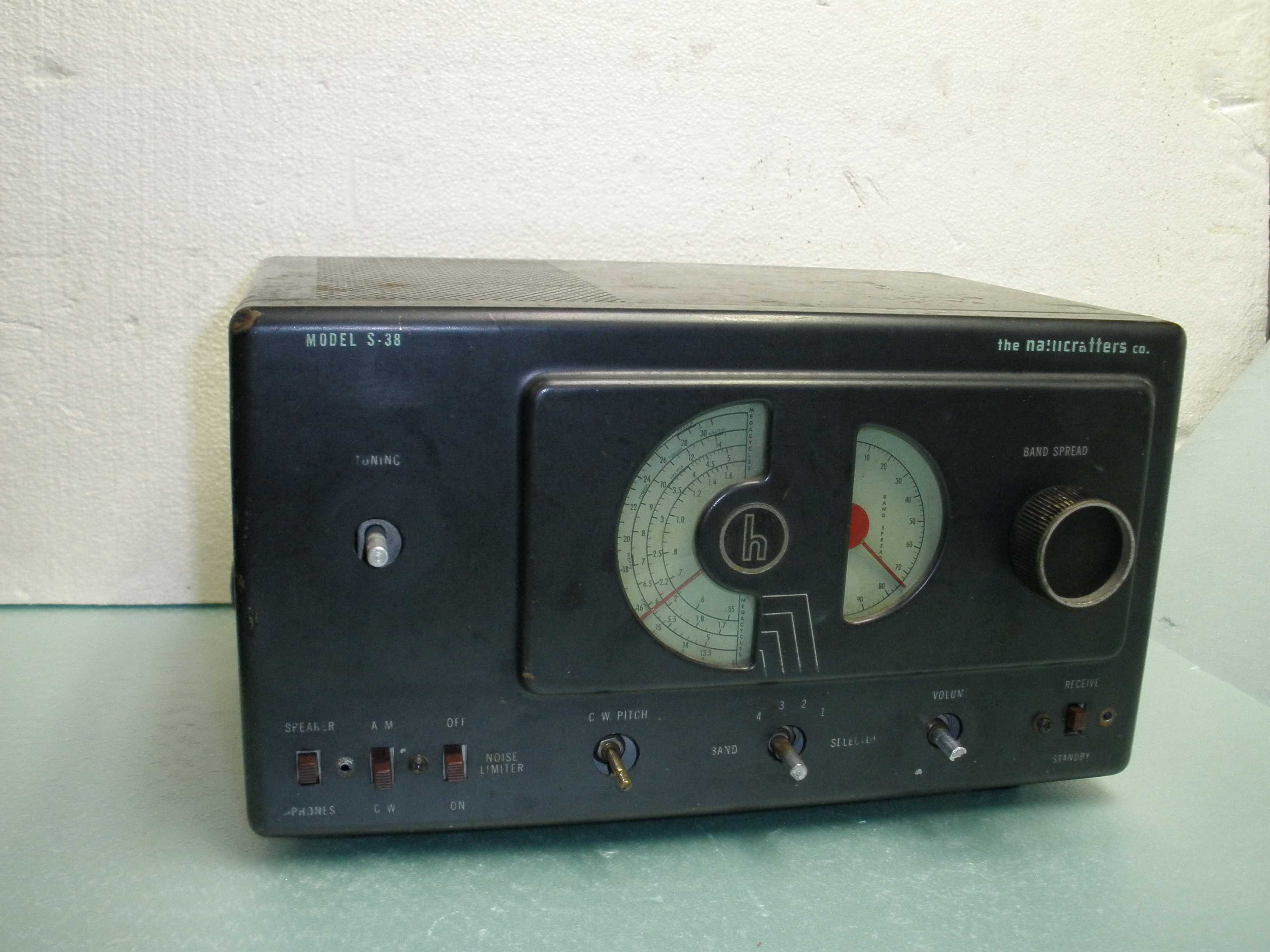
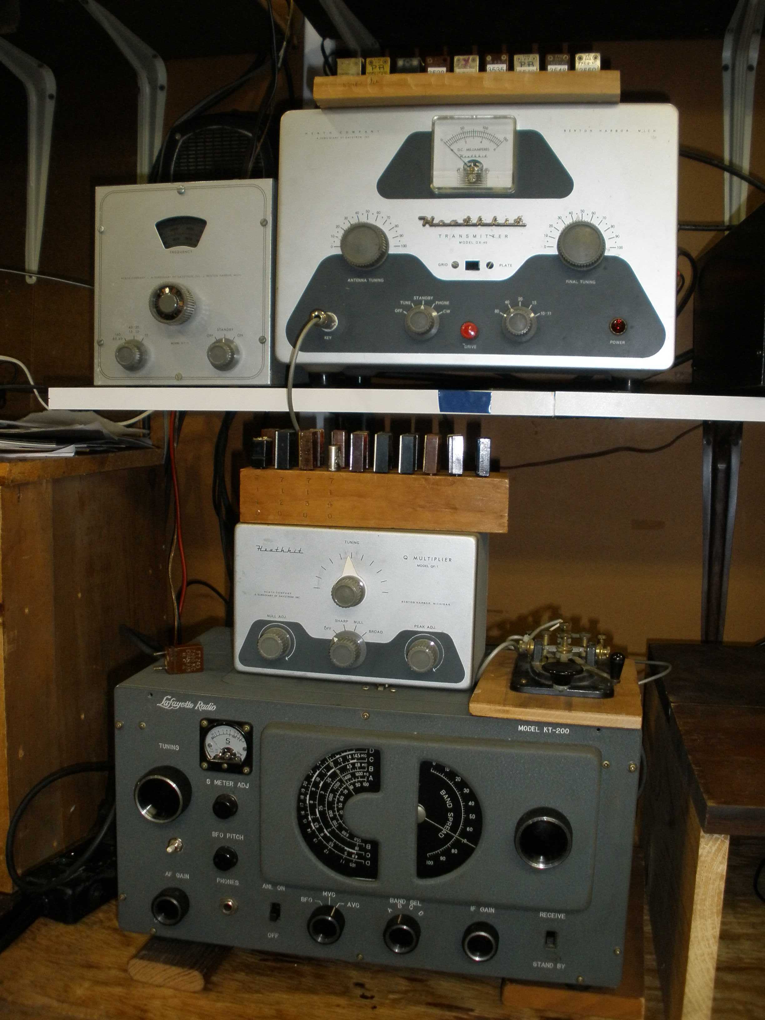
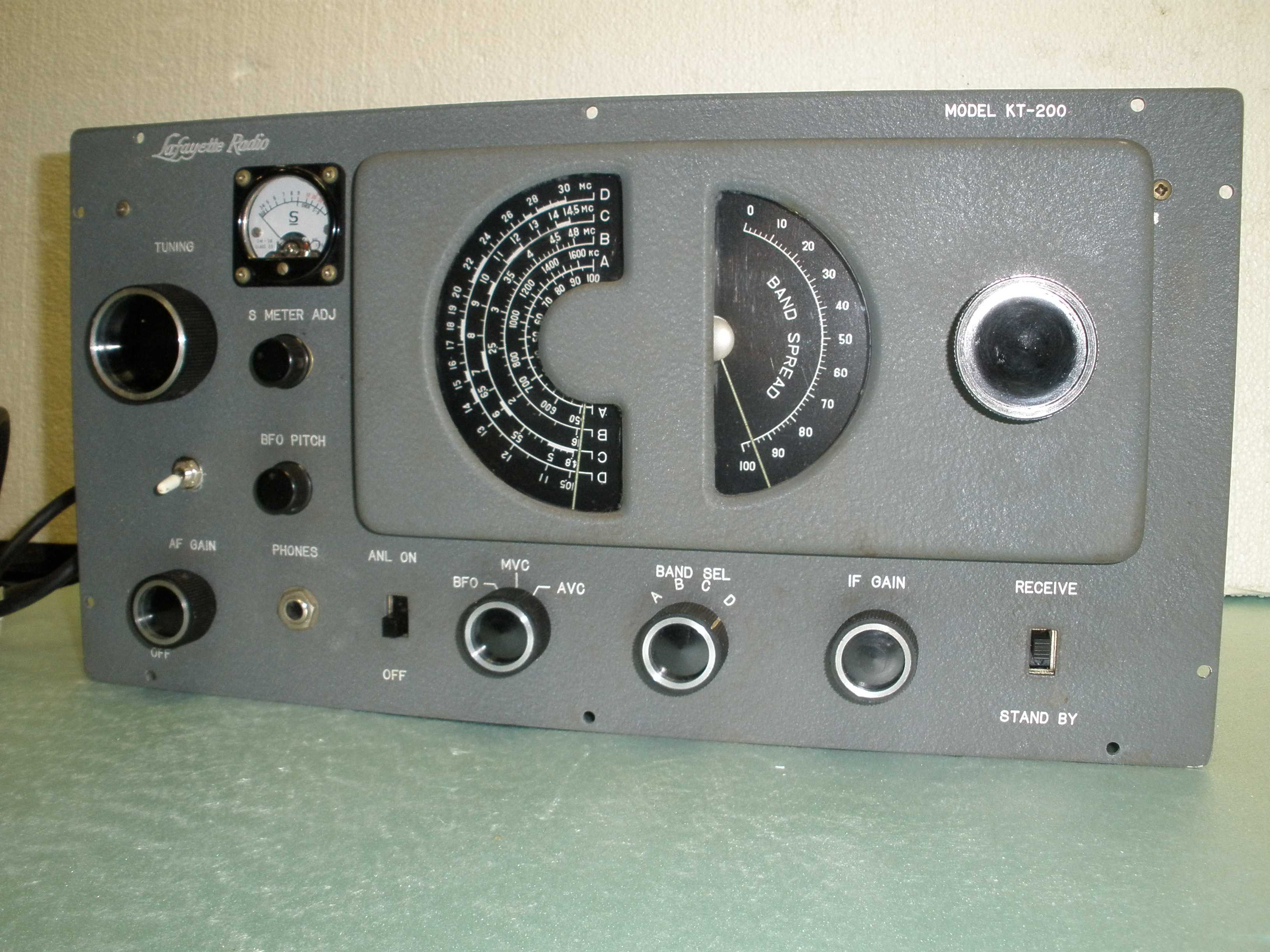
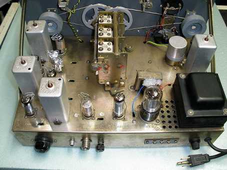
The Lafayette HE-10 shortwave receiver is often mistaken for the more common Hallicrafters S-38. Both were popular as a novice station receivers, as well as for shortwave listeners (SWLs). The HE-10 main tuning dial has markings for international short wave broadcast bands, to attract the SWL market. The HE-10 came in three notable versions, all indentical electrically. The Lafayette HE-10 shortwave receiver was the factory wired version. The front panel engraving said HE-10, if it was a factory wired unit. The KT-200 was a US market kit version, and its front panel was marked KT-200. The Trio 9R-4J was a kit version popular in the other countries, and in Ithaca, it sometimes surfaces because of international students bringing it into the area. In its kit form, it provided much more performance than the S-38, at the same approximate cost. The iconic half moon S-38 dials and knobs were created by the famous industrial designer Raymond Loewy. The Japanese manufacturer was trying to capitalize on that popularity and look. During 1959 to 1963, at a price of only $64.50, it was a great deal for a high school kid. It was replaced by the HE-30, which had calibrated band spread, and switched to the more popular "slide rule" straight line dials. Remember what a slide rule is? The performance for such a low price is why an HE-10 wound up in my novice station. I used this same station in the 2018 Novice Rig Roundup. Notice my extensive "Rock Collection" of crystals. The nice J-38 key has a base with rounded edges, and is marked underneath with a Lionel "L".
Who is Raymond Loewy? He left his mark on trains, automobiles, and many other iconic objects. I just found out that he also designed the Sunbeam Alpine. I once owned a Sunbeam Tiger (seen on the "Get Smart" TV show), the same car body with a Ford V8 power train. This car was fast and beautiful, and the cockpit had amenities found only on much more expensive sports cars. The drive train was the idea of none other than Carrol Shelby, before he created the Cobra. Before owning an HE-10, I was using a home brew regenerative receiver. As a teenager, I worked for the high school chemistry teacher washing glassware and preparing stock solutions for class experiments for a year to save up for this radio. Like others, I browsed through the catalogs of the day, and fell in love with the HE-10. I had experienced the S-38 at friend's shacks, but this HE-10 just looked like a radio that meant business. It had the styling of Loewy and the S meter gave it a WW2 surplus flavor. For sure, it was a big trade up from the regen set. It did not disappoint this Novice ham.
Read about Raymond Loewy's influence on modern society:
What are the advantages of the HE-10 over the S-38? First, the HE-10 had a power transformer, which eliminated possible shock hazard and reduced hum. Second, it had a tuned RF stage, adding sensitivity and image rejection. Third, it had two IF stages instead of only one. These IF stages used high quality iron core transformers rather than the air core transformers you usually find in the S-38. This provided much better selectivity. The HE-10 has an IF gain control, which the S-38 lacked. The HE-10 has a real BFO for receiving CW or SSB, whereas only the highly prized original S-38 produced in 1946 and 1947 had a BFO. The later S-38-A through S-38-E sets had a regenerative oscillating IF stage instead of a BFO, to reduce cost. The HE-10 has an S meter. The HE-10 does not have an internal speaker, though the S-38 did, a good idea because of safety reasons. Neither the HE-10 nor the S-38 have calibrated band spread, only a 0-100 dial. Its successor, the HE-30, added calibrated bandspread, and solved some of the design problems of the HE-10. The HE-10 used quality components and had good mechanical design, and so delivered better than average drift and stability than comparable contemporary receivers. The HE-10 has weighted tuning knobs, so you can give them a spin to move quickly in frequency.
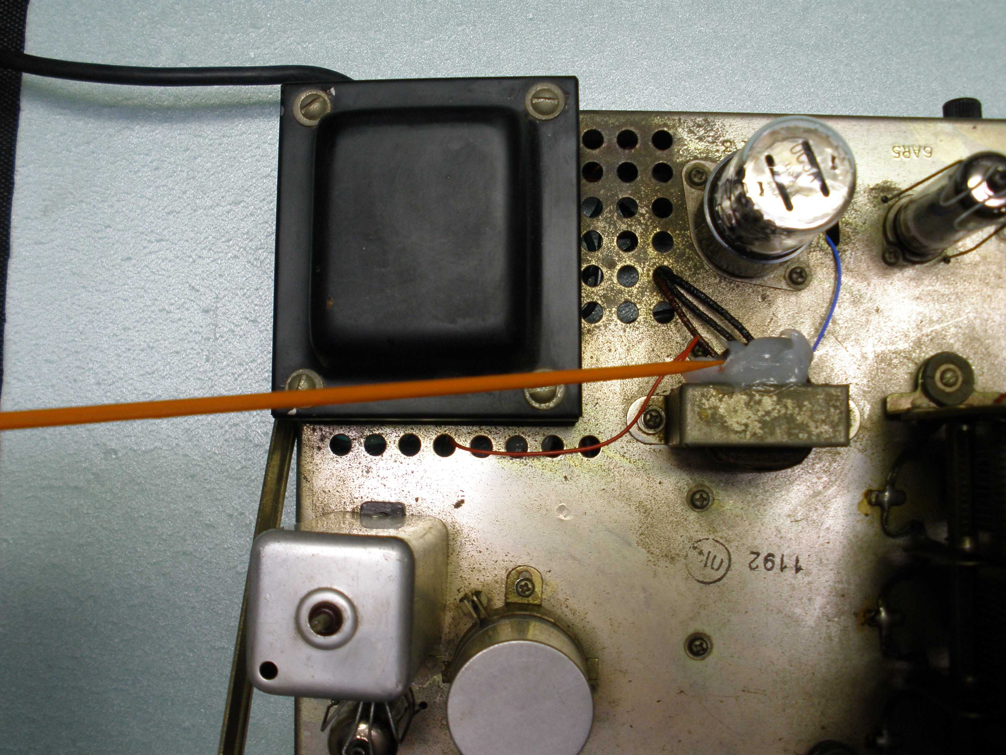
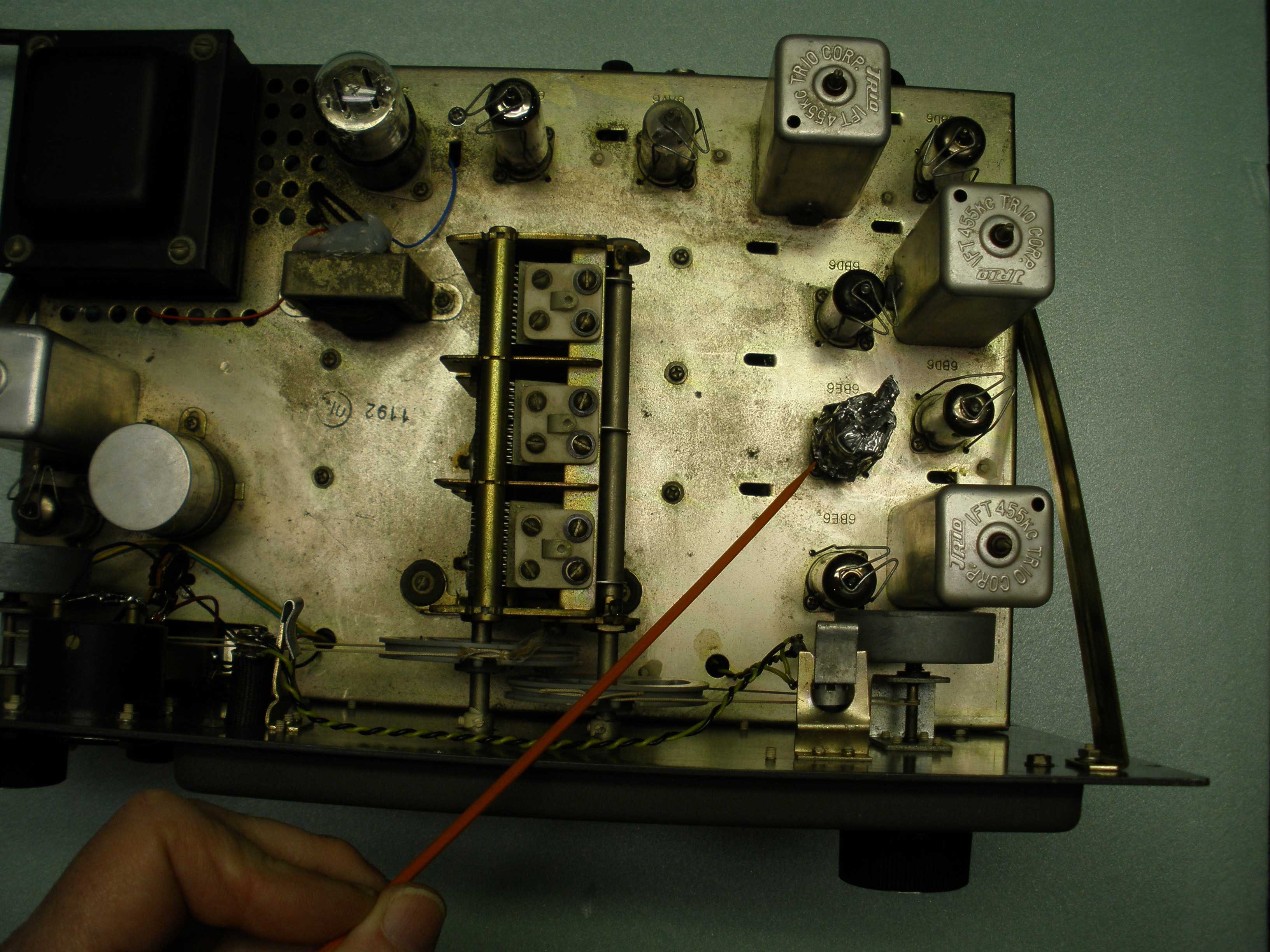
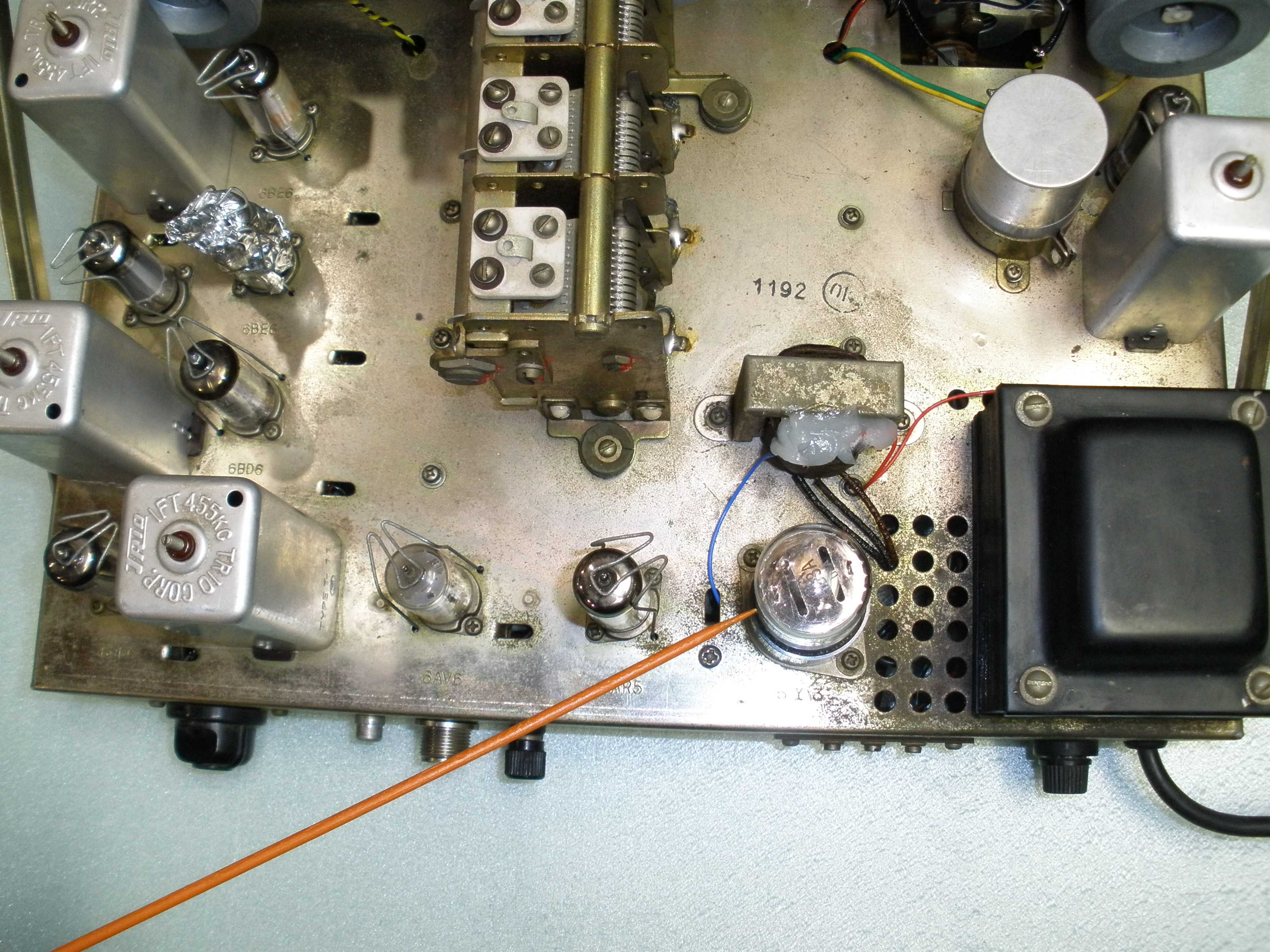
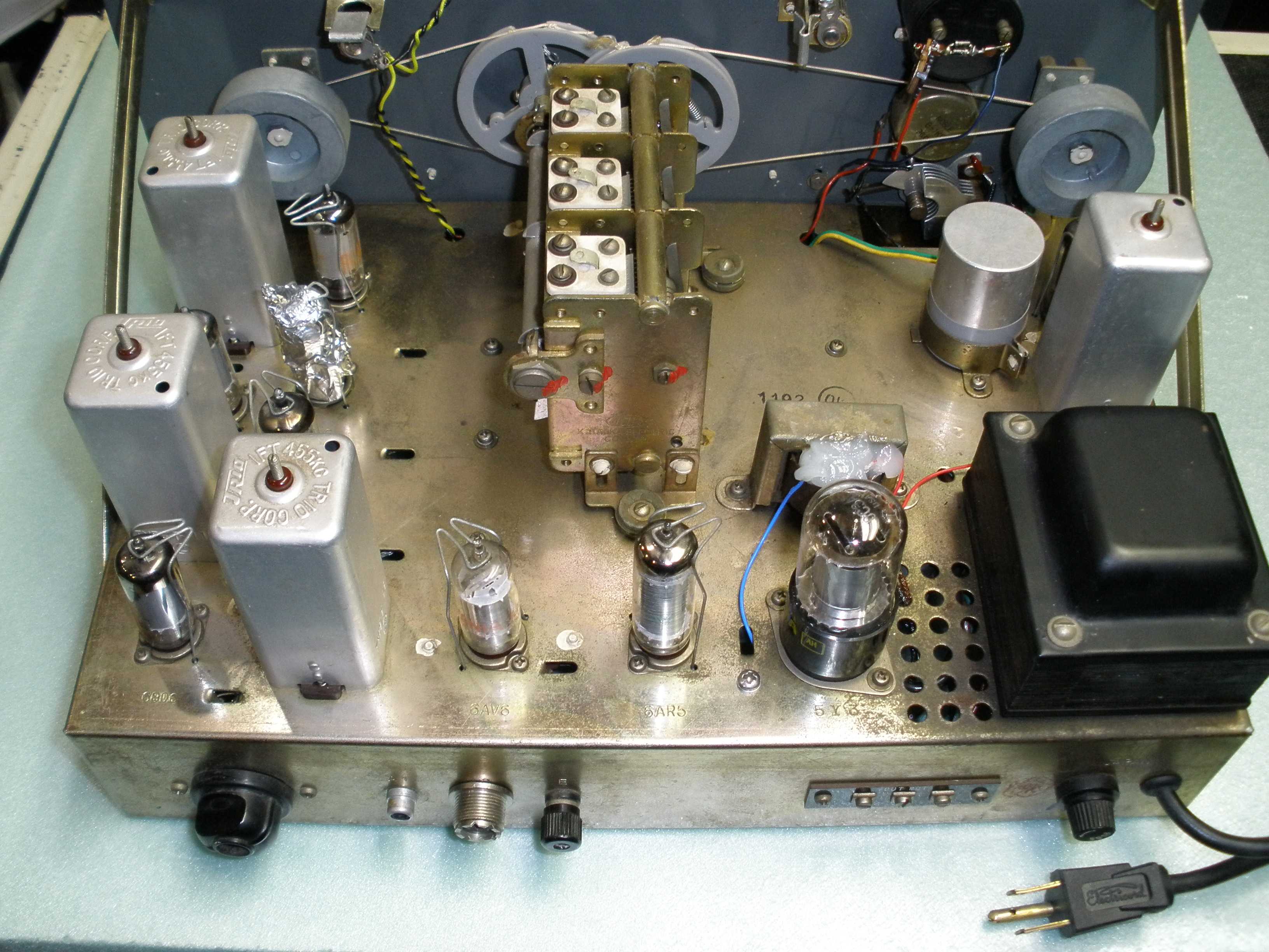
Unusual tubes were used, but there are substitutes. The 5CG4 can be subbed with a more common 5Y3. The 6AR5 can be subbed with a more common 6AQ5, with some adjustment. These are repackaged 6K6 and 6V6 octal tubes. The 6BD6 (similar to the 6SK7) can be subbed with a 6BA6 (similar to the higher gain 6SG7), but the circuits may oscillate unless adjustments are made. More on this later. Some of this is covered by a well written Electric Radio article, which restores an HE-10 and gives historical information. I used his information to do the repairs, then went ahead with improvements to the original design. I recommend that you obtain a copy.
Electric Radio #302 July 2014 - reprints from Ray@ERMAG.com
The HE-10 had some known deficiencies. The sensitivity was less than you might expect for a receiver with this many tubes and circuit complexity. The BFO injection was insufficient. The audio could be better. The CW note pulls badly on strong signals, and could benefit from a VR tube stabilizing the B+. The dial lamps and sockets need to be replaced with units that will not short the filament voltage. There may be some instability at the low end of the broadcast band. Given the low cost and this radio being the first in a long line of Lafayette shortwave receivers, you can forgive all this.
Bill Orr, W6SAI takes these issues up in a magazine article and alleviates some of the deficiencies, which I will reference later. Bill Orr is an experienced engineer and author of the Radio Handbook, a much more technical resource than the contemporary ARRL hand books. My results differed from the W6SAI article, possibly because he used a factory wired unit, and I had a KT-200 kit to work with. I found that the chassis layout with the RF stage near the IF output contributed to some instability, and had to back off some of the cathode resistor values that Bill Orr used to prevent oscillation in my radio. My bypassing methods differ. Most significantly, he uses the VR tube for most everything except the audio stages. I used the VR tube ONLY for the new product detector, the HF oscillator and the mixer, all the 6BE6s in the radio. This eliminated distortion from "pulling" of the oscillators on strong CW or SSB signals. This effect is caused by the widely varying B+ current drawn by the AVC controlled stages; my approach eliminates that problem. This is meant to give you an overview of this restoration and modification story as it unfolds.
73 Magazine June 1961, available on line at http://www.qsl.net/kb9mwr/files/ham/73.html
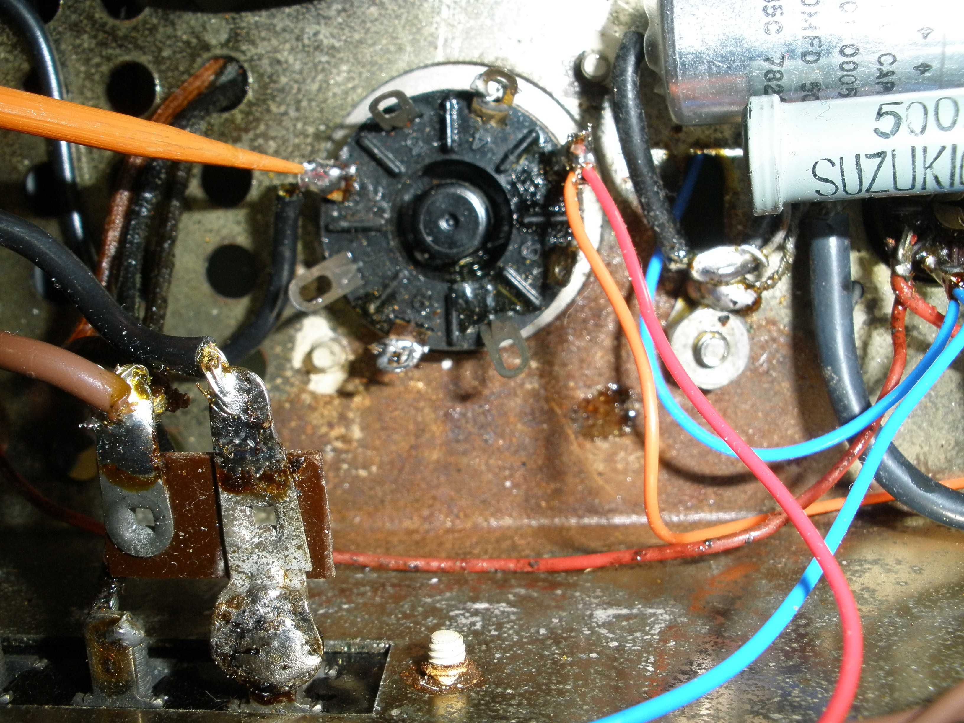
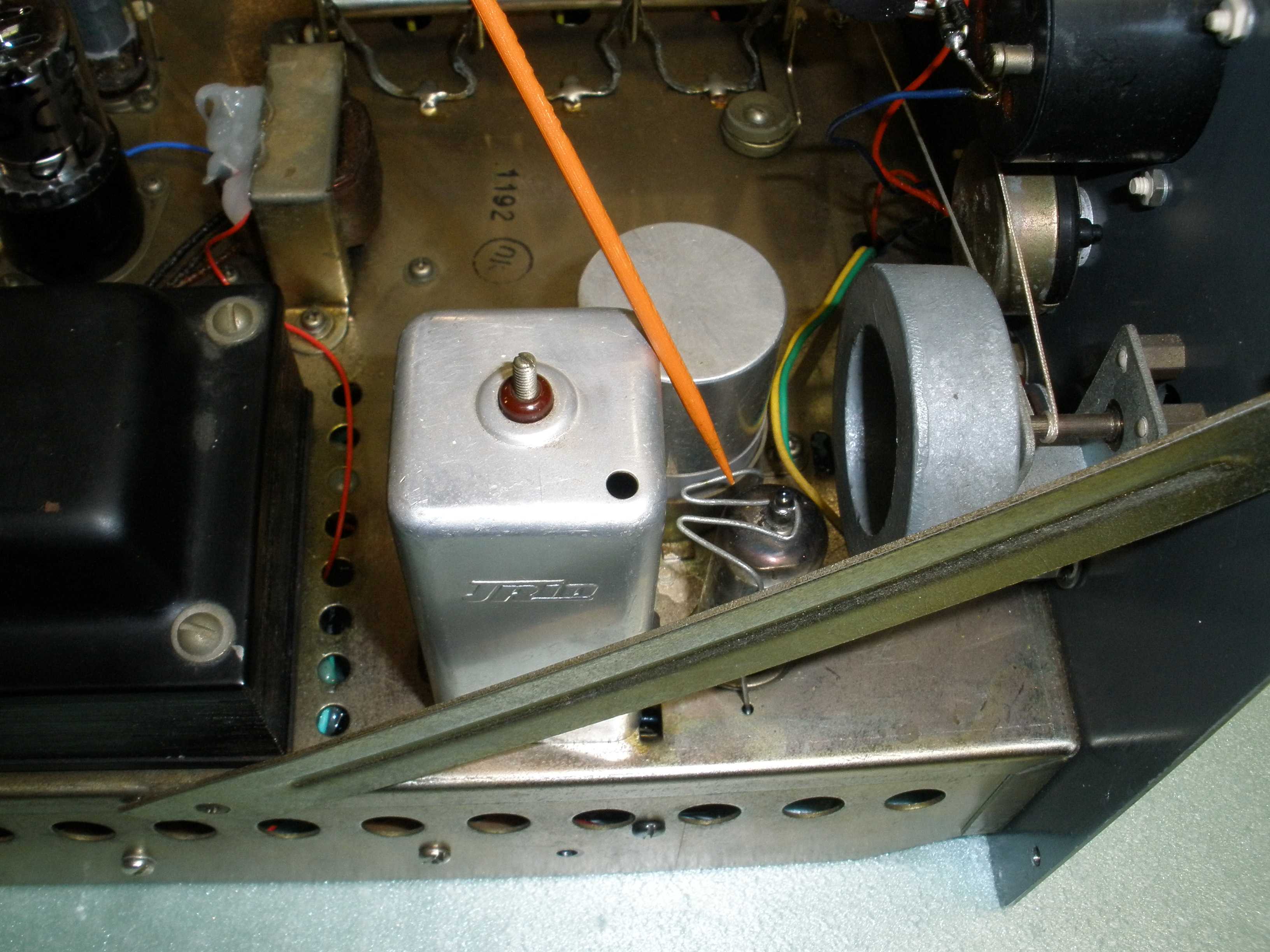
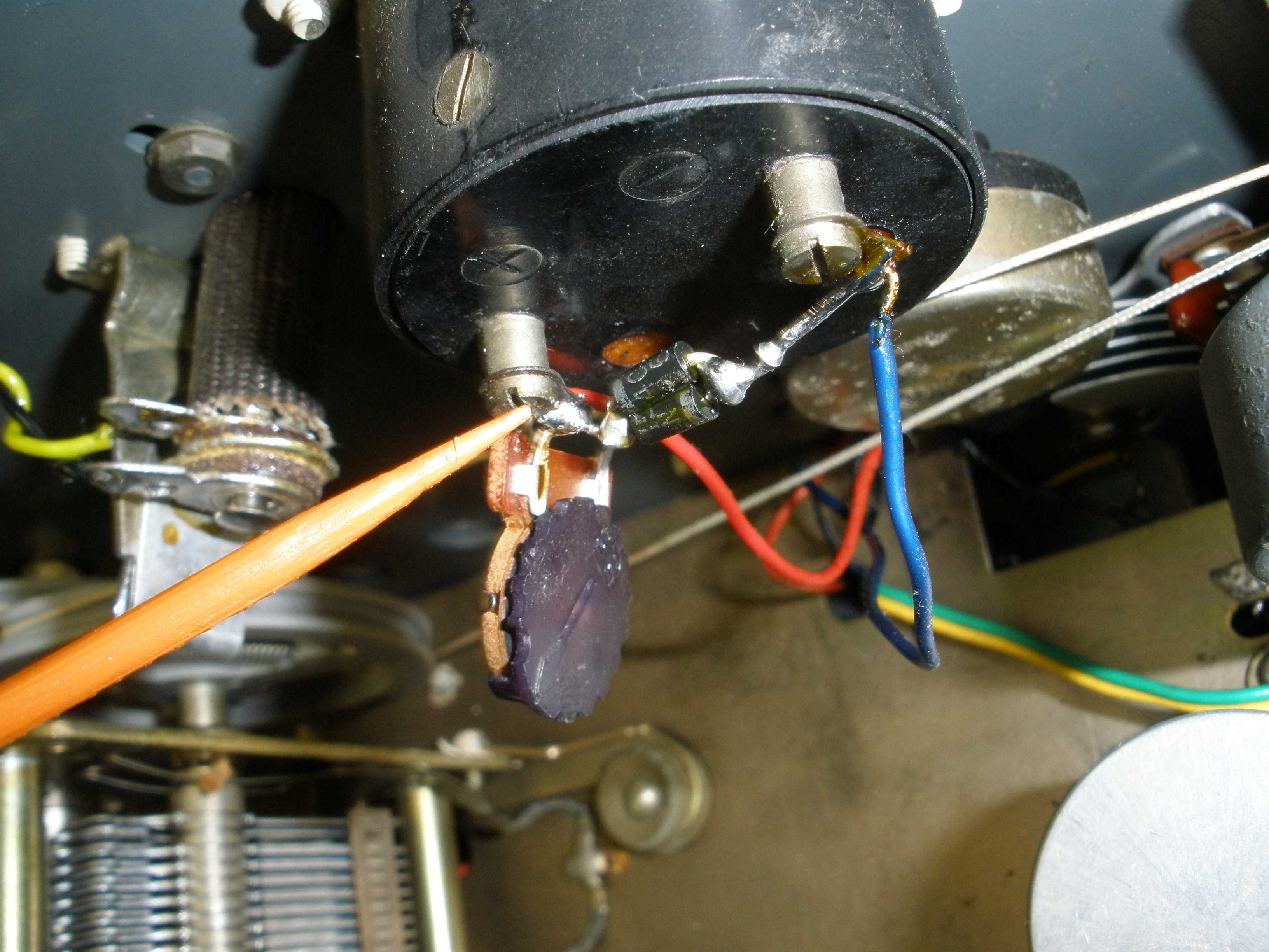
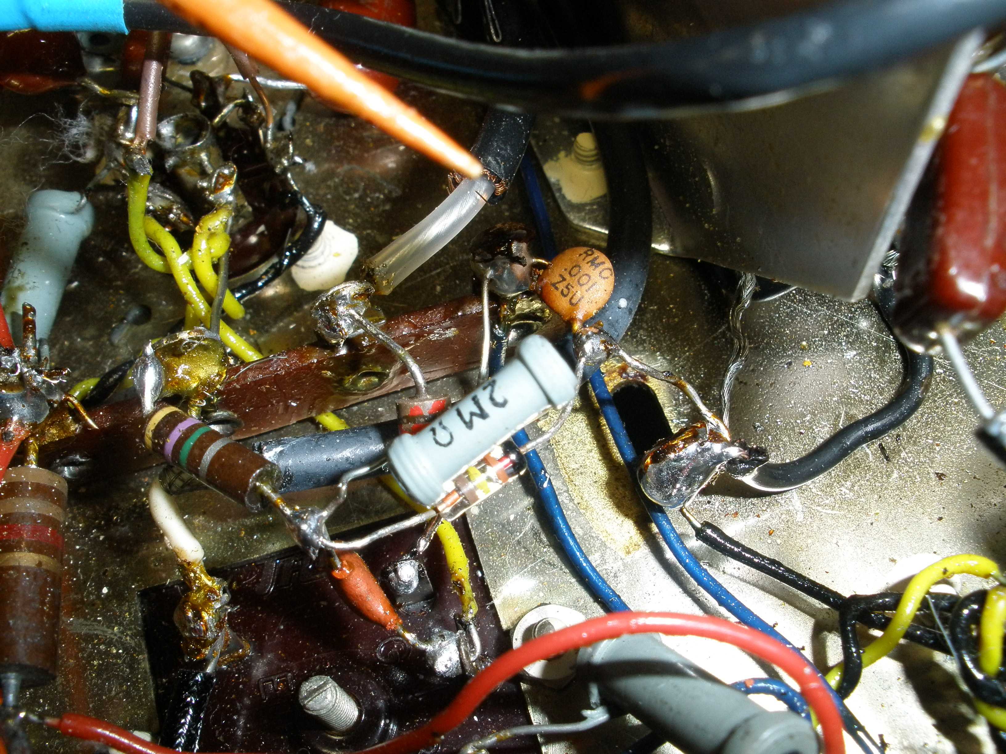
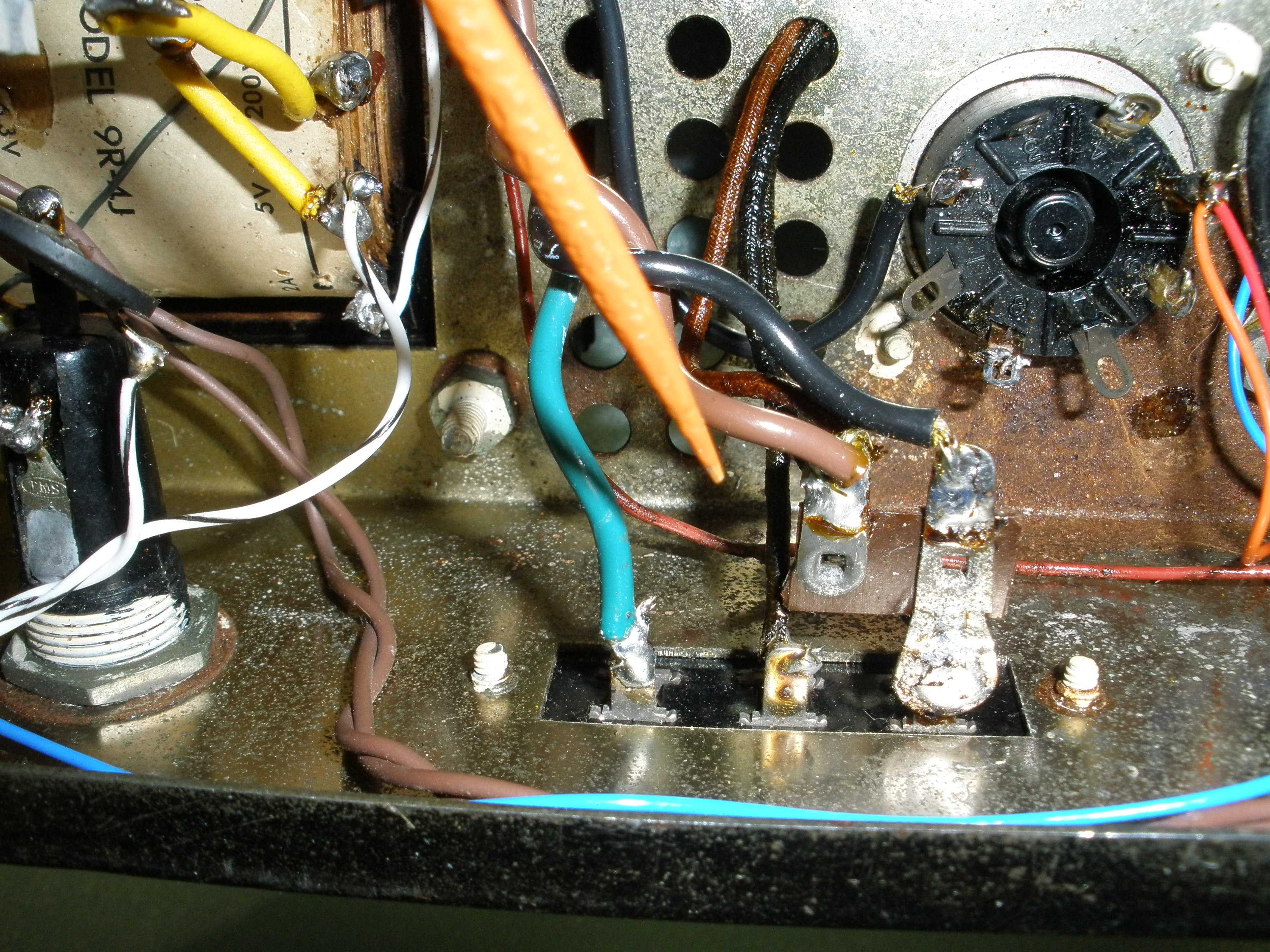
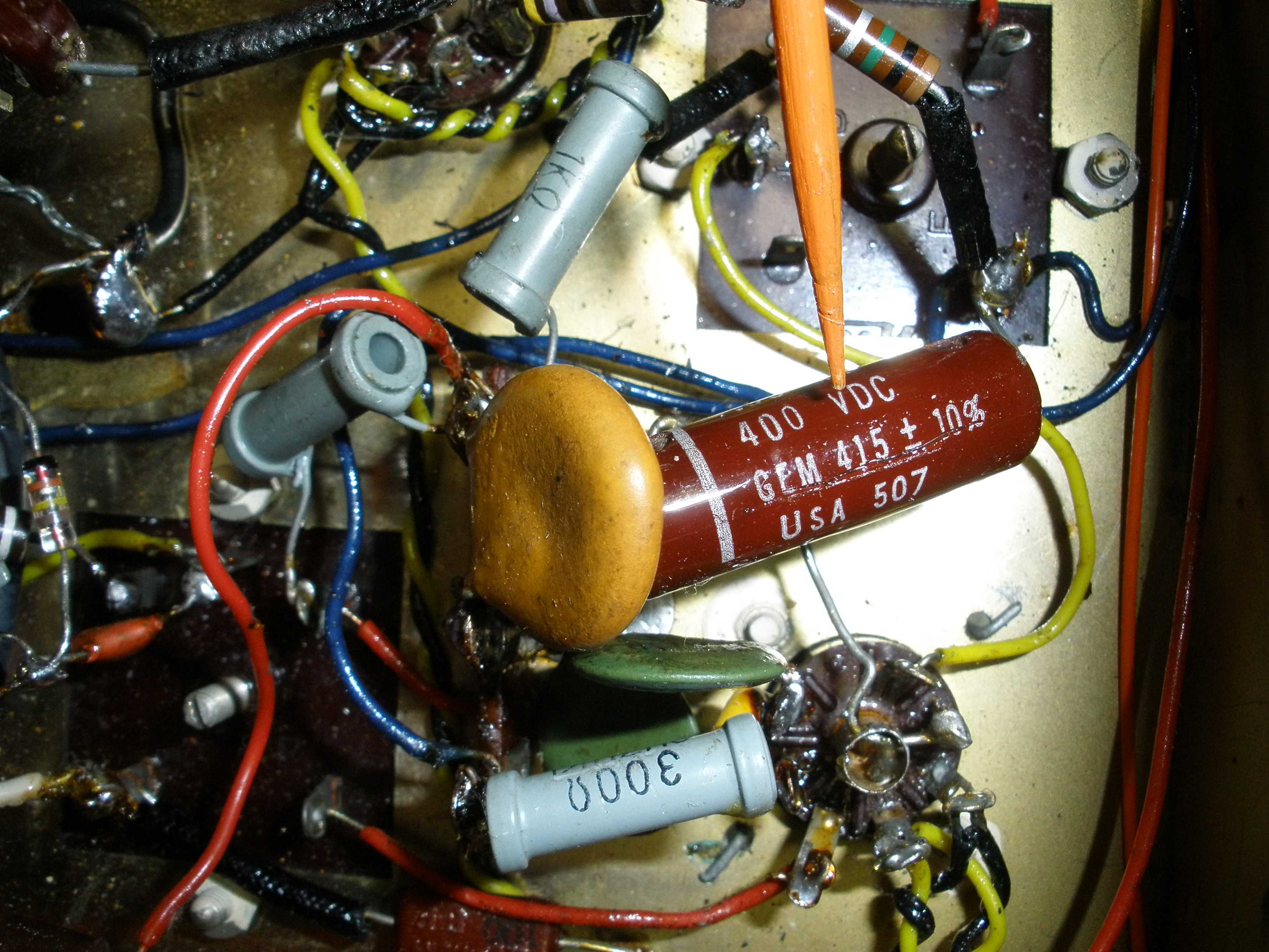
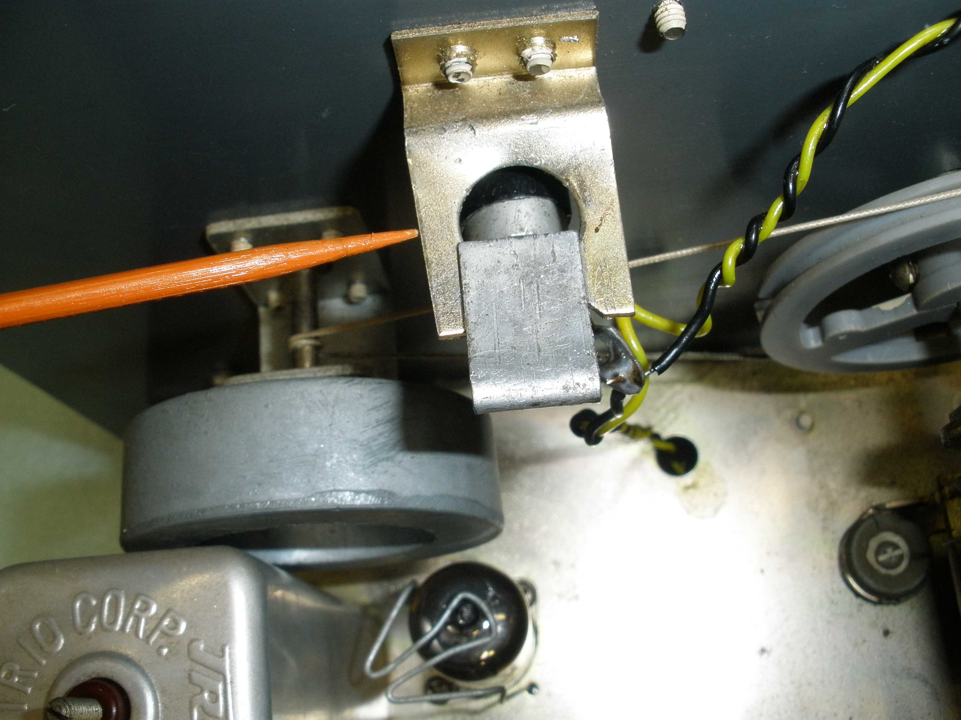
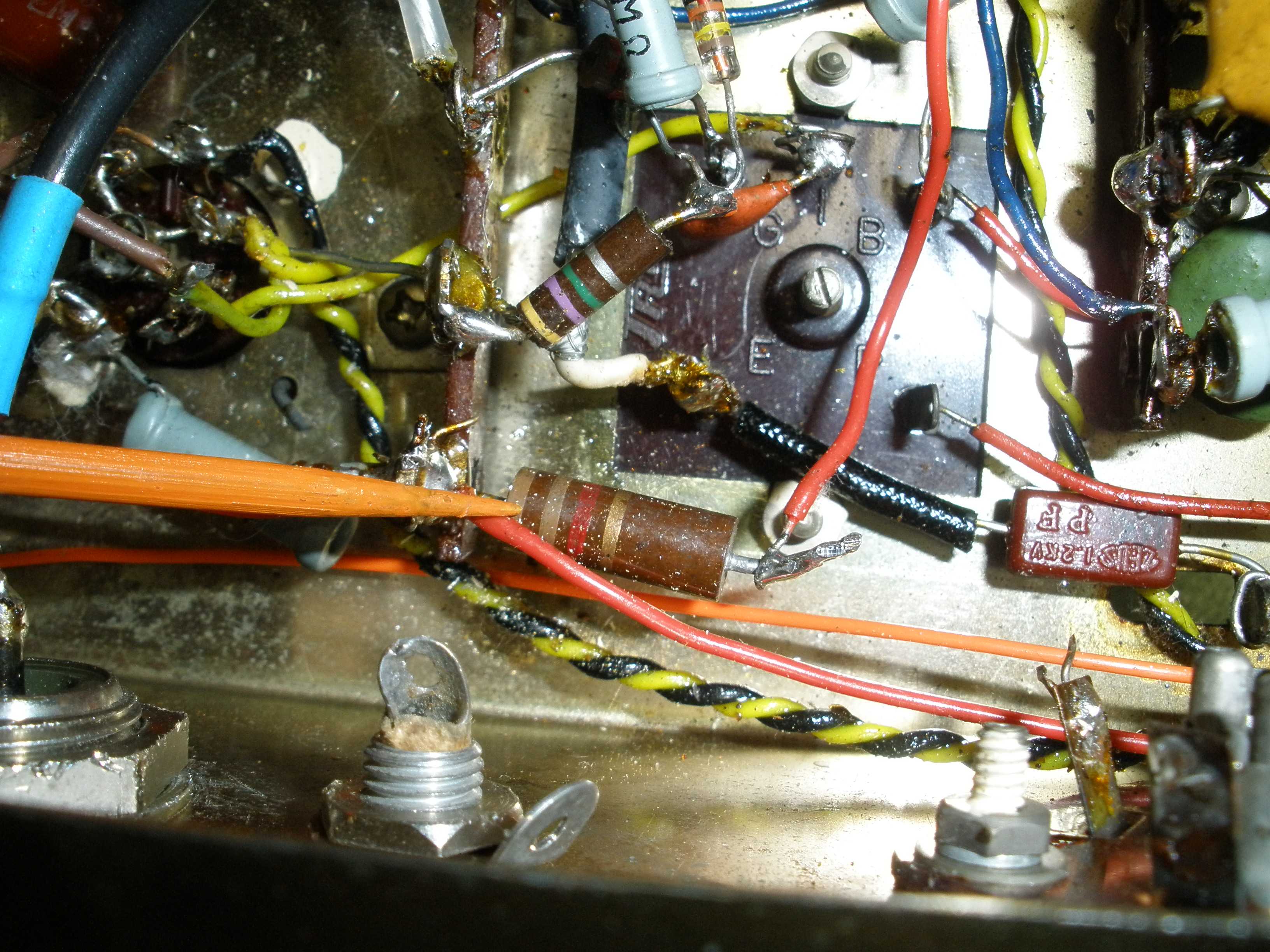
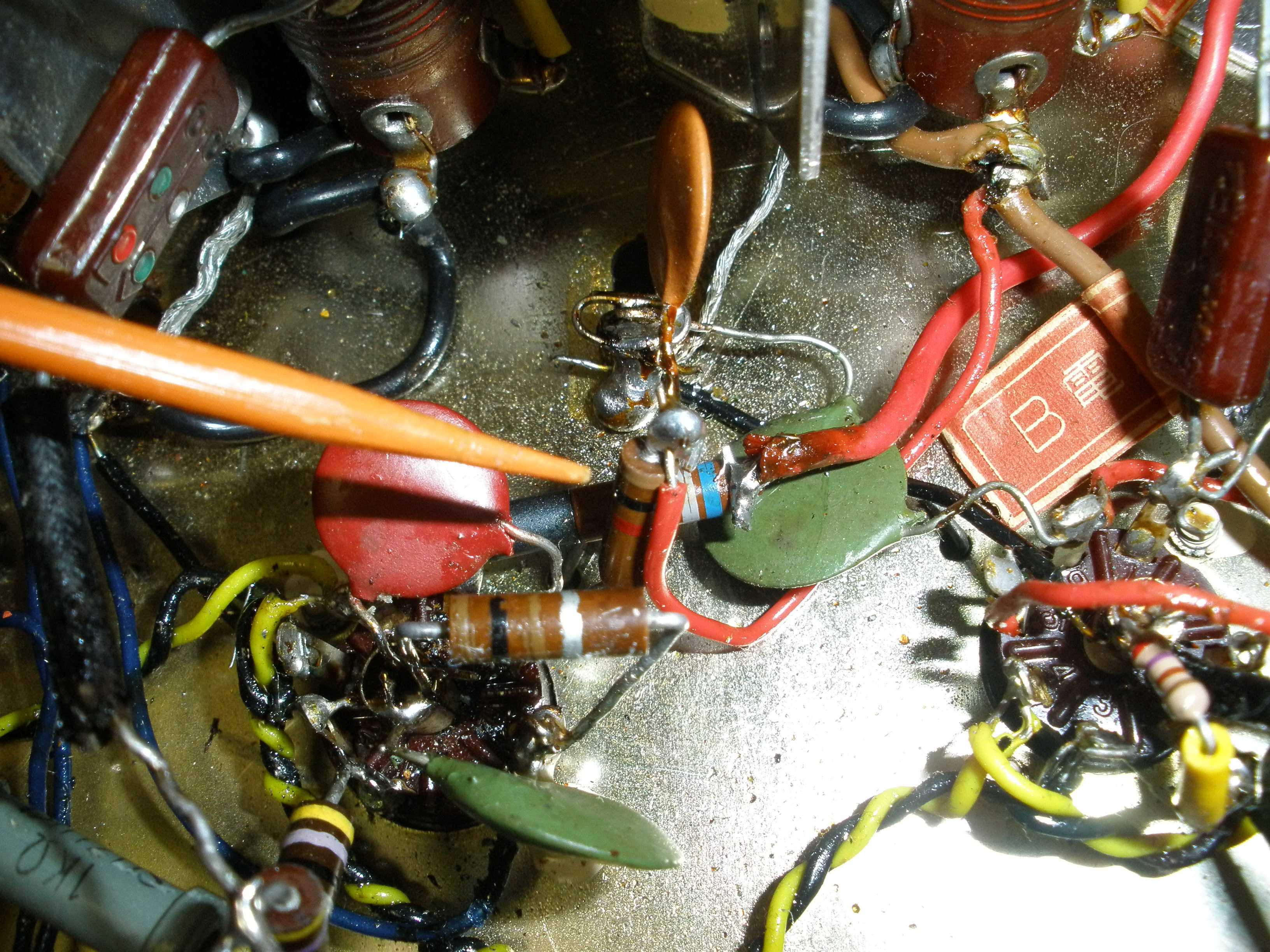
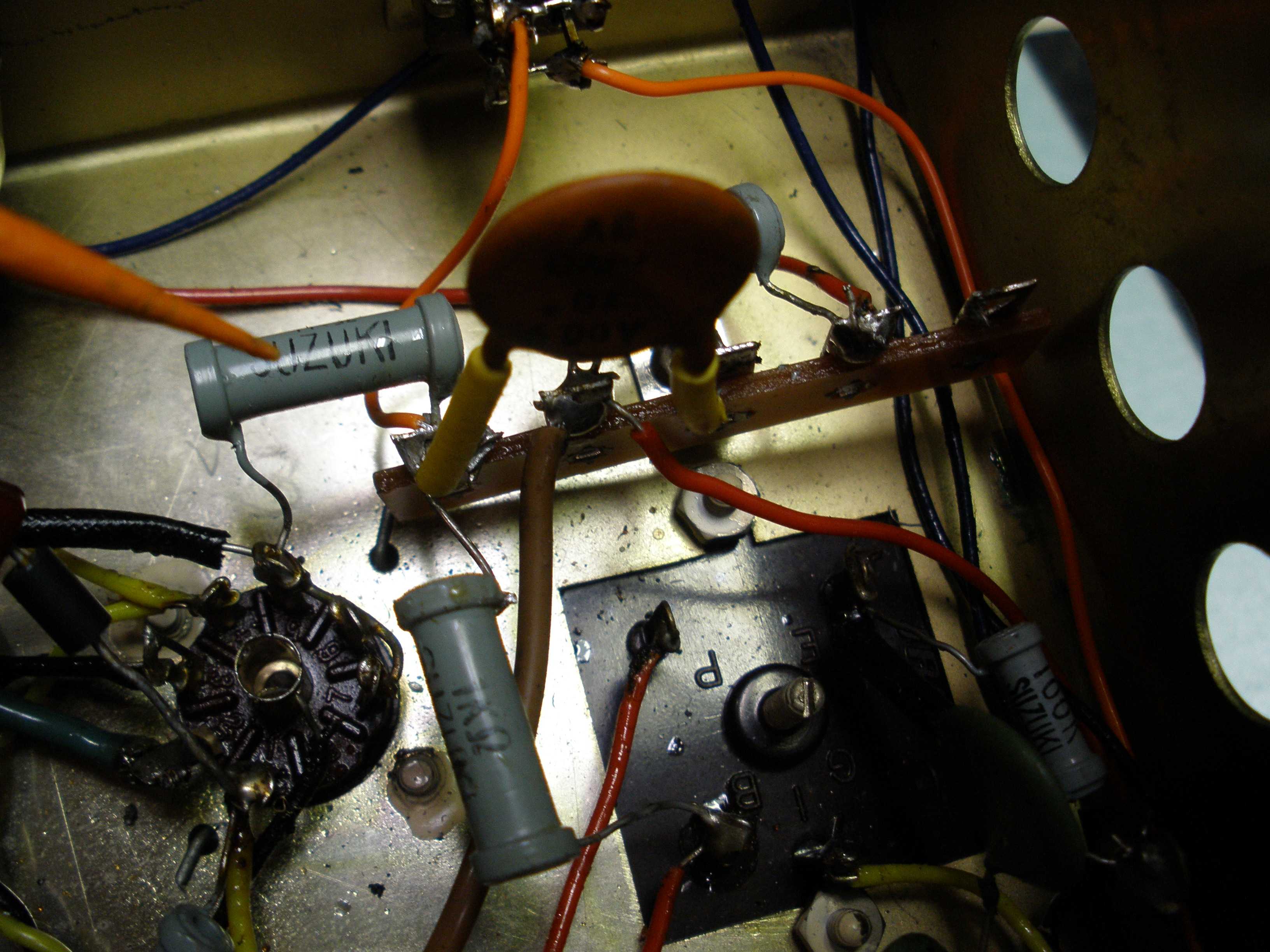
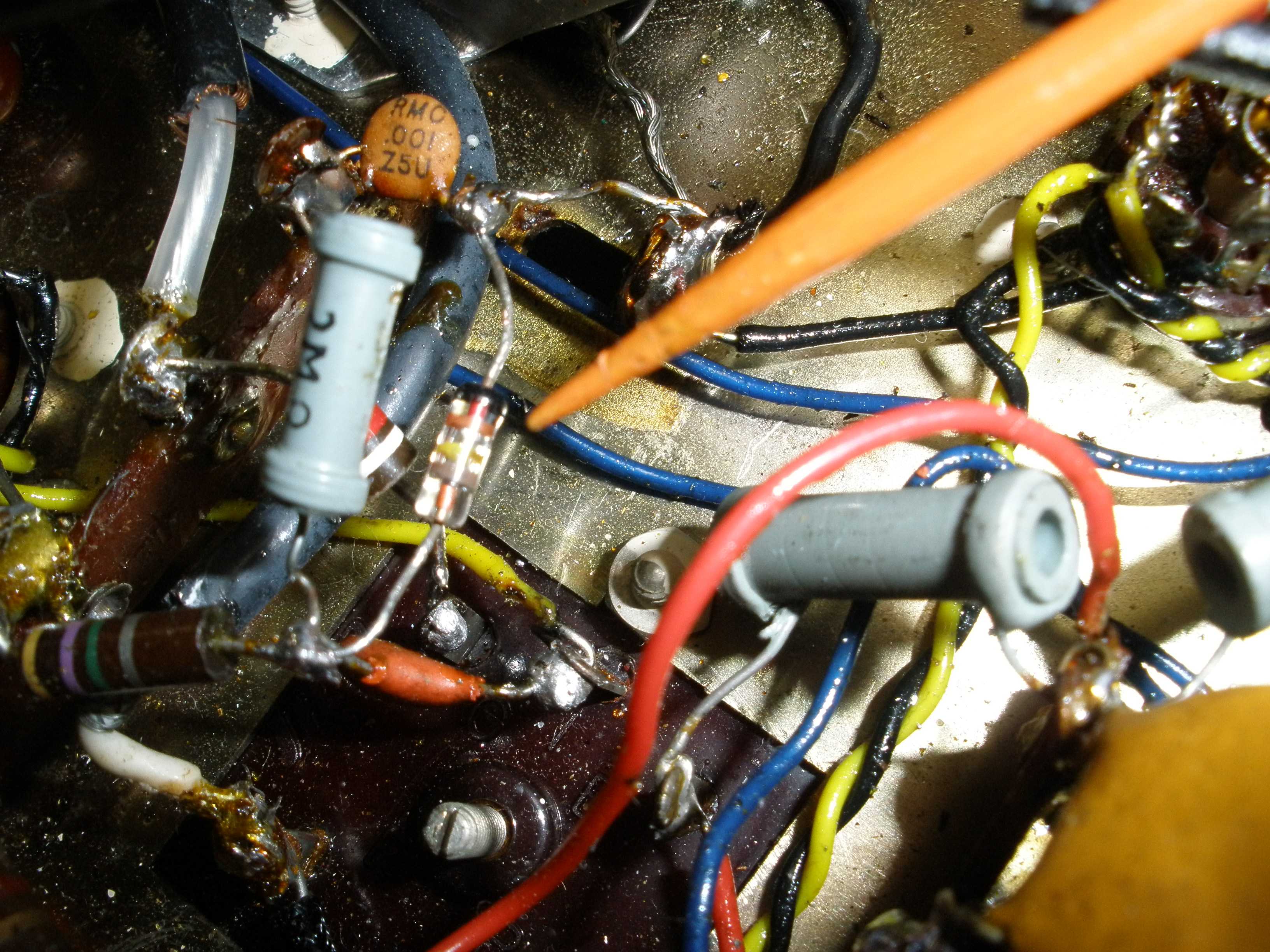
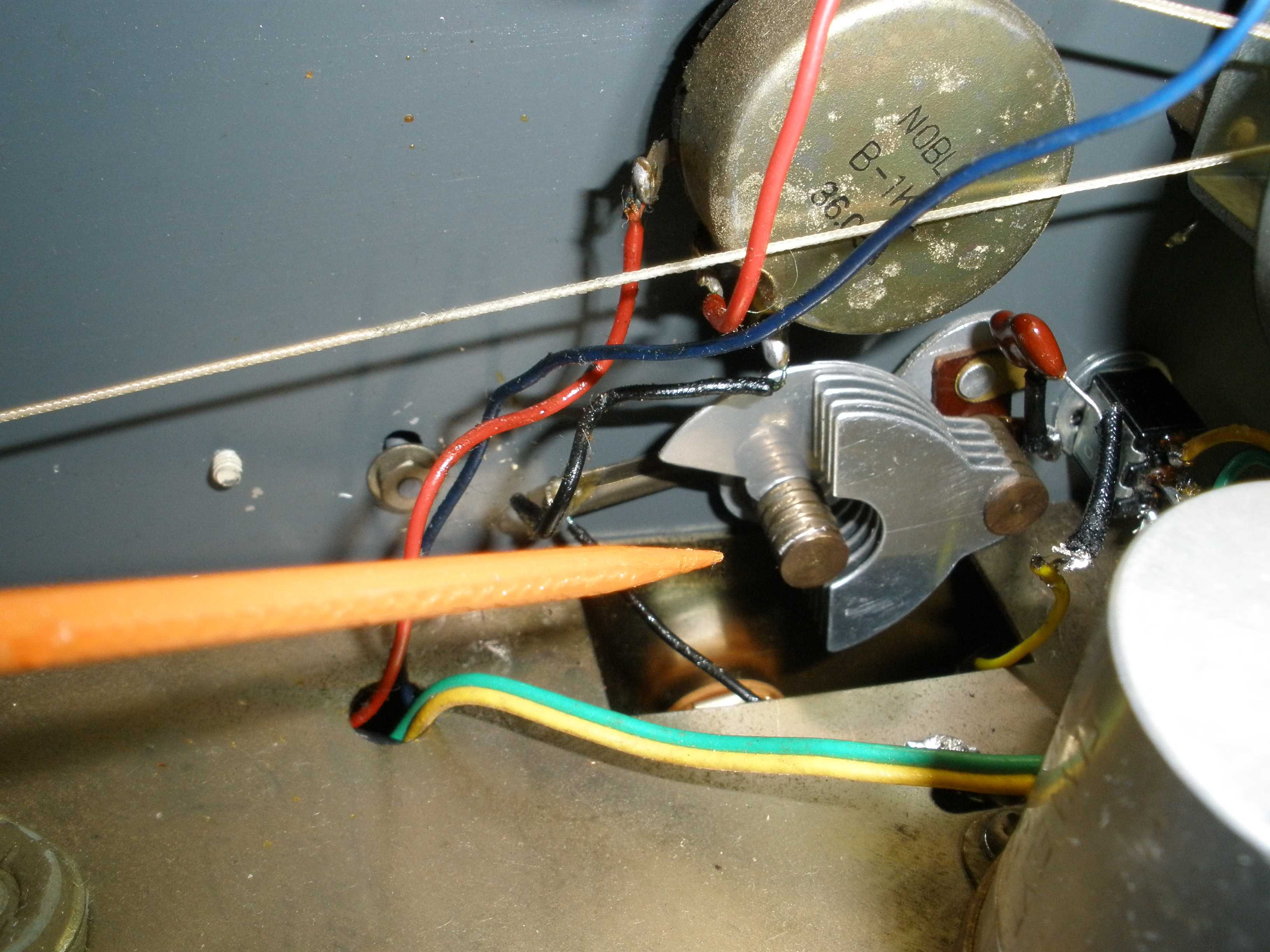
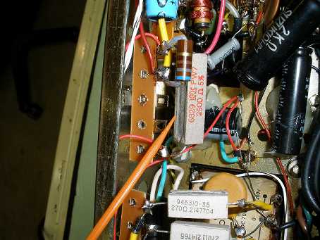
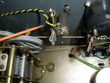
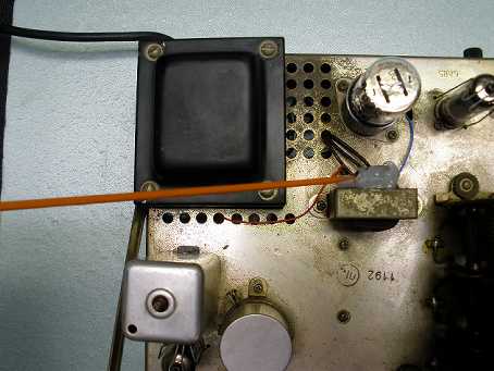
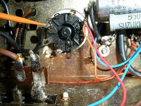
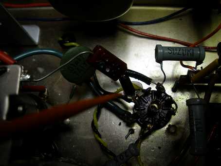
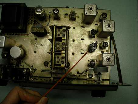
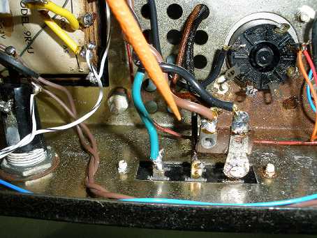
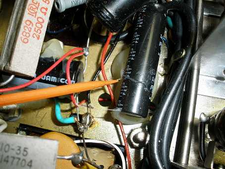
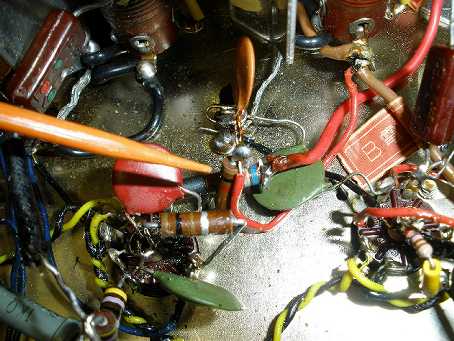
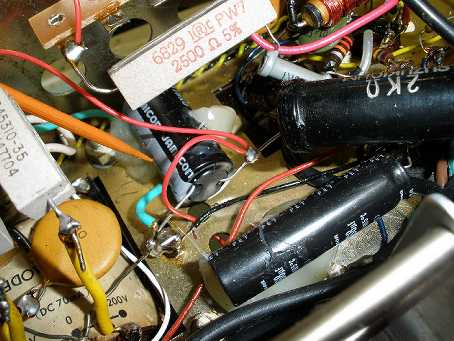
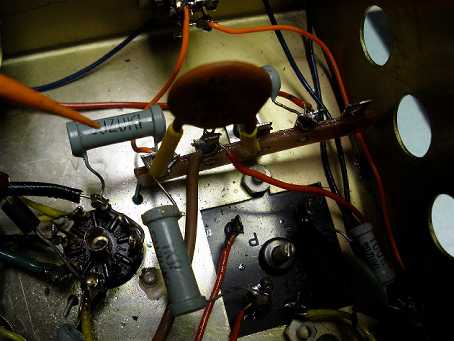
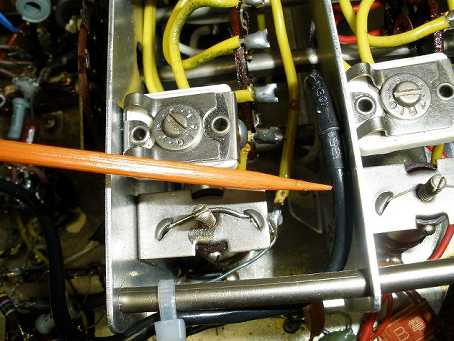
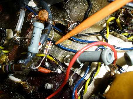
Before you go ripping into any vintage radio with a bunch of modifications, get the radio working in stock form first. The essential items to replace in this process are the electrolytic filter capacitors and four paper capacitors. One is across the AC line. One is across the B+ winding of the transformer. One is across the tube side of the audio output transformer. Do not forget the one from the 6AV6 plate to the 6AR5 grid. Do not bother testing these, they are all bad. I had one fail during the first year I owned this radio. These are the only inferior grade components you will find in the HE-10, and getting them done before you proceed will save headaches. The radio shown in some of these photos had at least 3 fires in it, before the original owner gave up. He had installed a 5 amp fuse. One of the fires was sloppy filament wiring, which shorted. The other fires were caused by capacitors. You can see the marks left on the chassis from these conflagrations. Once you get the radio operational, you can clean the band switch and slide switches with DeOxit or another quality contact cleaner. I strongly recommend leaving the pots alone, unless they are scratchy. After all these years, they still work, and have that characteristic smooth feeling to them when the HE-10 was new. I had to replace the badly cracked plate and B+ leads on the audio output transformer.
Once you can hear local AM broadcast stations, you are ready for a rough alignment. You should get the IF aligned to 455 KHz within a couple KHz or less. It is good practice to check it with a frequency counter, because this is the foundation of all the rest of the alignment process. Align the RF, Mixer, and Oscillator stages using the information in the manual. The coils for band D are closest to the Oscillator/Mixer/RF tubes. They progress down to band A as you get farther away from the front end. The manual does not tell you that. After all the restoration is done, I align band B for maximum sensitivity on 2 and 4 MHz to favor the ham bands. Then I align band C for best performance on 7 and 14 MHz.
Alignment of the highest frequency coverage, band D, requires a trick for best results. I have a lab grade grid dip meter; you probably do not. The oscillator frequency must be aligned to 455 KHz ABOVE the receive frequency for best signal to noise ratio and gain. People often bring radios to me that have neglected this important detail. Here is a simple hack to test if you have done the job correctly. With radios with only one RF stage, there will be an image (about 50 dB down) on the top band. If the oscillator is running on the high side, moving the signal generator about 900 KHz higher and switching out about 20 dB attenuation to increase the signal should produce a weaker mirror image. If the image is BELOW the desired receive frequency by 900 KHz, the oscillator is running on the wrong (low) side of the receive frequency. Do not get carried away with this, since any of the changes described below will mandate touch up alignment to get the best final results. Some of the simpler modifications can be done by themselves. The more challenging mods will require a higher skill level, and may require you to do ALL of the related mods to get the correct results. Some of the mods use concepts from Bill Orr's article on improving the HE-10, with my own observations on how to best implement them, and some details of his work that did not seem to work out for my radio. My work also takes the HE-10 well beyond his results, making this a true Novice Dream Radio.
I begin with the repair and simple improvements, moving to the more advanced modifications. This list should tease your curiousity, be patient, there is more to come:
- Three wire grounding power cord.
- 6BA6 RF amplifier and biasing for big improvement in sensitivity (goes from 10 uV to 0.5 uV).
- Install S meter protection diodes and S9 level calibration pot.
- Solid state power supply replacement for 5CG4.
- Use of the 5 volt rectifier winding as a bucking voltage to get 125 VAC down to about 117 VAC.
- Use the 5CG4 socket for an OC3 VR tube to run the oscillators.
- Reduce the IF and RF stage instability with better bypassing and power supply stability.
- Replace the 6AV6 BFO with a 6BE6 product detector for improved SSB and CW reception.
- Reduce range of BFO tuning for less touchy adjustment for SSB or CW.
- Provide AGC of various time constants for AM, CW and SSB reception.
- Improve AGC with delayed AGC for better weak signal reception.
- Add simple inverse feedback to audio output stage for less distortion.
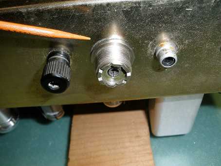
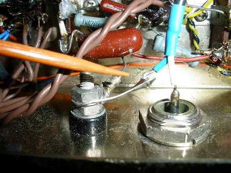
- Install a Coax antenna connector and wiring to improve stability.
- Add tube shields to RF and mixer stages. Use aluminum foil to avoid changing the tube socket.
- Add "tube saver" thermistor to AC line to control warm up time. Mouser # 527-CL90
- Addition of Heathkit Q multiplier for better CW selectivity.
- Install a more effective Bishop noise limiter to replace the original audio noise limiter.
- No extra holes in the front panel for mods (the white toggle switch was added by a previous owner).
- Full side by side performance shoot out between a stock HE-10 and the modified version.
- Could this HE-10 as modified be a poor man's HQ-129?
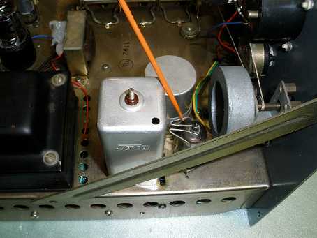
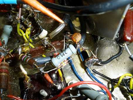
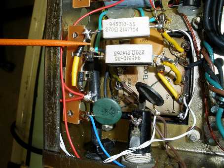
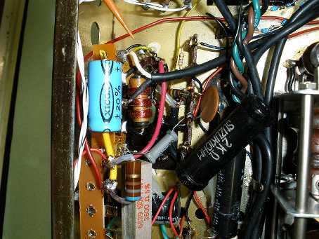
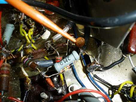
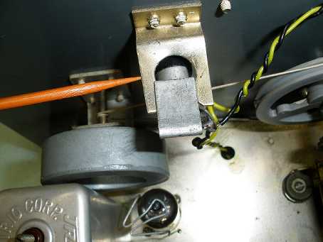
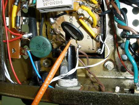
Here are the photos of my work, in no particular order. I will add commentary and schematics as the project unfolds.


|