|
WHY USE A FULL WAVE HORIZONTAL LOOP INSTEAD OF A DIPOLE ON 160, 80, 75, 60 and 40 METERS? (Rev 6/2017)
A dipole antenna just will not work unless it is at a sufficient
height. The multiband dipole I describe in another article could have
another wire added for 160 Meters. But the repeating resonances at 2
MHz intervals would have detracted from its performance. Even if you
managed to get it to ¼ wave up at 160 Meters, about 70 feet,
it would be problematic. The extended G5RV and other flat tops are
just dipoles with a different feed method. For that matter, the off
center fed types like the Carolina Windom are the same stuff. End fed
long wires must be hung at similar height to get the performance to
be heard well. A height of 120 feet or more is required for long haul work. Even for NVIS close in work, the ground loss increases as the antenna gets lower to the ground. ANY antenna works better if you raise it higher, up to about half wavelength above ground.
A full sized vertical would be a mechanical monster, and cost a fortune. Even the commercially available top loaded 160 meter vertical is a project to install. It requires a lot of radials, too. Or the
loading coil would reduce bandwidth and radiated signal. I did a
helically wound 160 Meter vertical about 25 feet tall, but it was
like erecting a wet spaghetti noodle. And it was mounted over a
ground screen which used up two ¼ mile rolls of electric fence
wire. Some of the ground wires were 700 ft long in the direction of Europe. It did work for DX, but was lousy for local ragchews beyond
ground wave distance. At high noon, I was able to talk direct to Long
Island with 100 Watts AM during the summer to another station using a
similar vertical on ground wave. A helically wound 80 and 75 meter vertical did quite well over the same ground plane wires. One winter night, I was heard in India using about 500 watts output on 75 meter SSB. I was unable to copy the other station since he was lower power, but it was quite a thrill.
If you hate to climb trees and you have no tower, but want to work short haul with a good signal on 160 or the lower frequency bands, try a horizontal full wave loop. I do not address the use of a loop as a multiband affair. Some people use open wire line and feed a 80 or 40 meter loop on multiple frequencies. Using a 160 meter full wave loop in that fashion is likely to be counterproductive. I found a 60 meter resonance for this 160 loop (third harmonic) and it did not work as well as a low dipole cut for 60 meters. I have the luxury of enough land to have wire antennas optimized for each band. Further, a loop in any orientation is inherently broader band width than a dipole.
There is some mythology about NVIS or Near Vertical Incidence antennas. LOWERING any antenna most always increases ground loss. The reason people run low dipoles is to SUPPRESS longer distance communications at lower take off angles. Also, when you reach a half wavelength above ground with a dipole, a null appears at high angles, preventing NVIS communications. A dipole a quarter wavelength above ground provides mostly high angle radiation without that null. Any lowering of the dipole antenna below 1/8 wavelength does not help short range communications, since ground loss increases. Of course, at 160 meters, 125 feet is a quarter wavelength, and such a tower structure is beyond my reach financially. Many people use lower dipoles successfully on 160. I just maintain that at low elevations, a horizontal loop will provide equal and usually better local NVIS performance than a dipole at the same height. When propagation is extraordinarily good, winter during a sunspot minimum, double hop can occur at longer distances at times. Note that the vertical pattern of a dipole changes radically as height is changed above 1/4 wavelength or 125 feet on 160 meters or 65 feet on 80 meters. The horizontal loop vertical pattern stays relatively constant, only decreasing in ground loss as height is increased. Note that all the work shown here can be scaled to 5 MHz (60 meters) or 7 MHz (40 meters) for NVIS work with a better signal. A reasonable installation of a full wave horizontal loop at 25 to 50 feet for 60 meters can be used safely without risking interference to communications among primary users of that band compared to what might result from the lower angle radiation of a dipole at 90 feet (which is perfectly legal). If you are worried about the 1 dB theoretical gain of the loop over the dipole, crank back the power output of the rig to 90 watts PEP. Remember that an S unit is about 6 dB, so it is unlikely to show measureable difference in the real world. The close in performance of the horizontal loop (NVIS) might give you better regional communications than a dipole of equivalent height. The map below indicates the region where the full wave horizontal loop performance is optimum, and better than or equal to a dipole of the same height, up to about three eighths wave length elevation. A low dipole will continue to provide some useable single hop communication beyond the shown blue circle perimeter, depending on propagation.
The blue circle is approximately 900 miles range centered on Ithaca, NY, and beyond about 600 miles radius (the red circle) the loop radiation drops by about one S unit (6 dB down) from the primary lobe maximum (straight up), but is still comparable to the dipole at the same height. The loop theoretical radiation is 1 to 2 dB better than a dipole of the same height (half an S unit). My own experience is that it outdoes the dipole better than that. Outside the blue circle response drops off rapidly for both the dipole and the loop.
Here are links to a web site that compares HORIZONTAL loop performance to a dipole at the SAME height. His conclusion is: "Good NVIS gains are available from a broad range of heights starting at 20 feet up to 45 or so feet. The loop always beats the dipole by about 1 dB. This isn't much, but if you are QRP every little bit helps." I use his pattern graphics to obtain an approximate horizontal loop performance for the circles generated on the above map. Both loop and dipole at the same (lower) height lose performance beyond the blue circle, but the loop is still consistently better than the dipole at the high angles.
http://www.hamradio.me/antennas/nvis-gain-of-loop-and-dipole-vs-height.html.
He also compares a low loop with an added ground reflector wire:
http://www.hamradio.me/antennas/40m-loop-ground-wire-test.html.
Here are his patterns and gain for a low 40 meter dipole with a ground reflector wire. Note that with a folded dipole, narrow band element at 5.5 feet, with a ground reflector wire, he improves performance to nearly that of the 35 foot elevation with NO ground reflector. I prefer to just get the dipole to 30 to 40 feet, but in a portable installation, you may find his method applicable to your circumstances:
http://www.hamradio.me/antennas/40m-mastless-nvis-antenna.html.
Based on his data, I decided NOT to install a ground reflector on my 40 meter dipole, mostly due to the extra complexity and difficulty mowing the lawn. The extra performance did not seem to be worth the extra work and inconvenience at my height and circumstances. On 80/75, it might give enough improvement to be worth my work at the current installed height I have for that band.
NOTE: Do not get confused with data for VERTICAL PLANE loops for DX work; this web page is for HORIZONTAL PLANE loops for regional NVIS use. There are some excellent resources for the DX use. QST June 2016 page 45 advocates the case for a dipole; the gist is the VERTICAL loop average height is lower than the identical dipole or inverted V and therefore low angle gain is lower and ground losses higher. W8JI also has an excellent discussion of VERTICAL loop performance. He also explains the term dBi (gain over a non existent ISOTROPIC antenna that antenna manufactures use to confuse the unwary). For instance, if you are comparing a beam antenna to a dipole, you must subtract at least 8 dB from a beam rated in dBi. A dipole delivers a little over 8 db gain over an isotropic antenna or 8 dBi. A loop delivers approximately 1.5 db more than a dipole or 1.5 dBd (dB referenced to a dipole) or a little over 9 dBi. But W8JI focuses his discussion on VERTICAL plane loops and low angle patterns for DX.
See https://www.w8ji.com/delta_loop.htm.
For the same amount of real estate and only a quarter wave height above ground, you can get more low angle DX gain than a dipole or vertical plane delta loop from a Half Square antenna. See:
While the trend today is to rely on mathematical models to evaluate antenna performance, there are some actual on the air tests using WSPR, which gets you a lot of data quickly on antenna performance. I favor practical empirical results, because they are real world results, rather than artificial models based on a number of assumptions used to construct the equations. Also, there are various software packages available, some of which do not include all the professional tools available to paid versions. This can influence the accuracy of the modeled results. I still have a dog eared copy of ON4UN Low Band DXing that advocates corner fed delta loops for 80 meter DX work. I admit it is disturbing to see such iconic work fall before some computer program output, especially since many hams used these antennas successfully. I encourage you to still experiment with antennas, since that is one area that hams can try ideas out. The innards of the radios are not accessible to most hams these days. There is a story that some computer analysis of the bumble bee concluded that it was impossible for them to fly.
QUARTER WAVE 75 OHM COAX QUARTER WAVE MATCHING TRANSFORMER (Q SECTION) FOR LOOP ANTENNAS
A full size loop exhibits a feed point impedance of approximately 100 to 200 ohms, depending on shape and height above ground. Matching such an impedance and driving it with a feed line without excessive line loss presents another problem. Happily, it is easy and inexpensive to solve.
In Ithaca, I have to run over 200 feet of coax to get the loop away from
the power lines to get quiet reception. Part of that length of coax is a 75 ohm quarter wave length matching transformer. I
eliminated all that loss that would have resulted from SWR caused by using 50 ohm coax all the way.
DO NOT WASTE MONEY AND RF ON A BALUN FOR THIS ANTENNA. The tuner (if needed) and quarter wave transmission line transformer
take care of it. Nope, no open wire line either. Balun??? We don't need
no @#$% balun! RF going somewhere is better than heat going nowhere. True, the q section only works on one band, in this case, 160 meters. You can use an 80 meter horizontal loop on 20 meters if you feed with open wire line. A 40 meter horizontal loop may work on its harmonics. I have a antennas optimized for each band because I have enough space and trees for supports. I prefer separate resonant no compromise antennas. Yes, the open wire line
has less loss in dry weather. Not so much in wet weather. The mechanical
hassles, losses, and costs are substantial compared to a simpler more reliable coax feed. And the balun is lossy, never achieves balance, and balance does not matter anyway. Why save a
couple dB in the feedline and throw it away in a balun and lossy antenna tuner?
There is a better way. Use a quarter wave matching section. Order up some
75 Ohm coax from DX Engineering. Put a connector on one end of about a
quarter wave of the coax. Using a MFJ259B, shorten the open end till you
get zero reactance and a zero resistive component at 1900 KC. Then install
the other connector. This works out to around 104 feet, accounting for the
velocity factor of the coax. The actual length of the coax is shorter than
the calculated wavelength because the wave travels slower in the coax than
it does in free space. This got me to a point near the house where I could
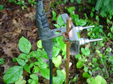
transition to 50 ohm coax. I installed a grounding stake and a lightning
grounding bracket from DX Engineering before I brought it in the house. See the
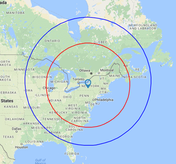
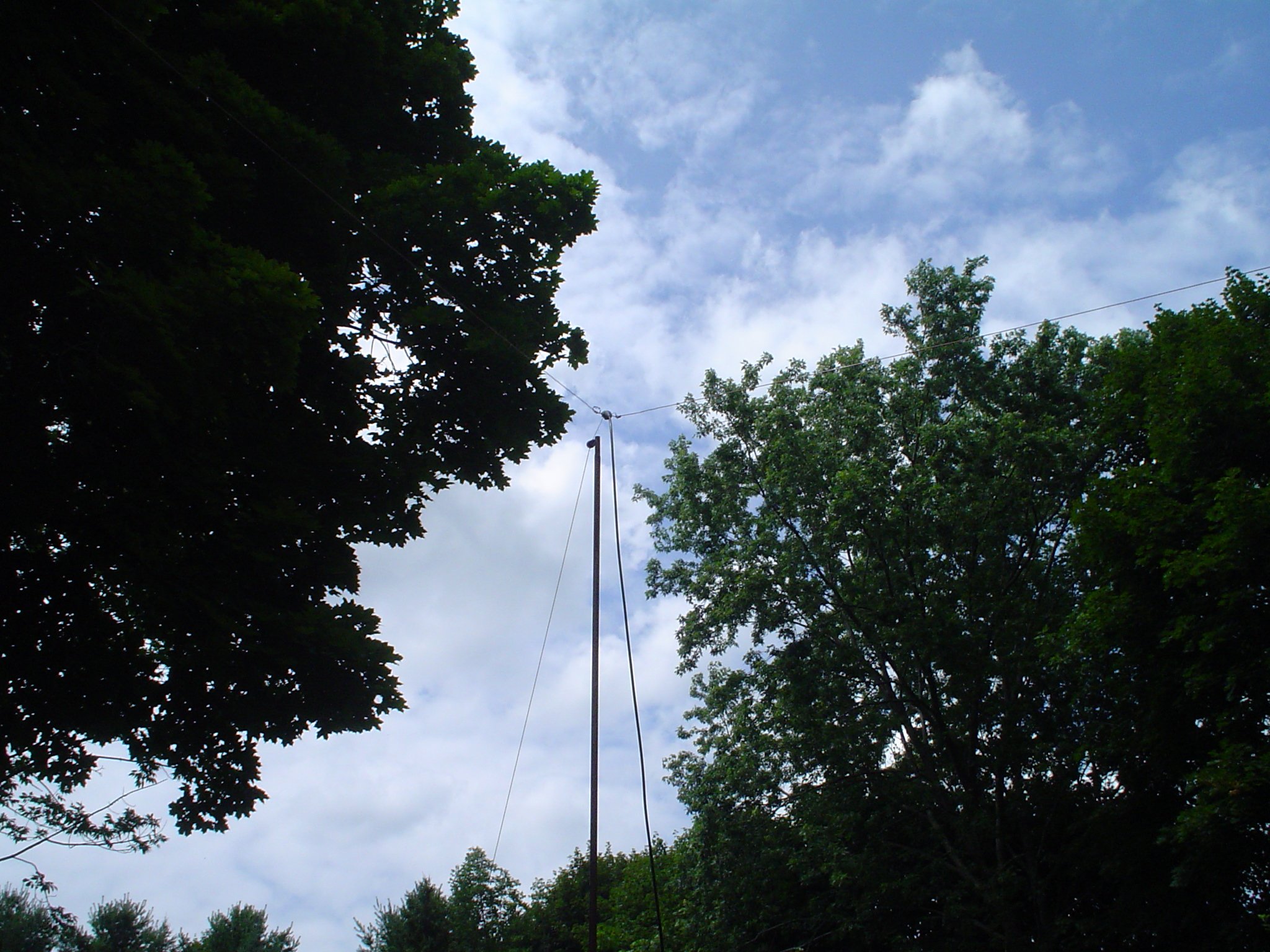
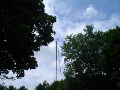
pictures for details. One photo shows a 20 ft length of TV mast which has been raised to a nearby tree at 35 feet height.
I will furnish some minor math to make your head hurt later. But here are
the pictures.

THEORY AND CONSTRUCTION - ITHACA LOCATION, WAS 10 FEET HIGH, NOW 35 FEET HIGH
The theoretical length for a full wave loop is:
| Circumference (in Feet) = 1005 / Frequency (in Megacycles) |
|---|
This works out to a total length of wire of about 529 Feet at 1.9 MHz. This wire is available as
a spool of STRANDED #12 or #14 THHN wire at Lowe's for less than $50. Use
black insulation for stealth. The wire will not cut to formula length
with insulation, but it is a starting point. I found that 504 Feet, about 5% smaller, due to insulation velocity factor, was correct for mid band 1.9 MHz. I wanted slightly above mid band, to favor 1.885 and 1.945, the common AM frequencies in this area.
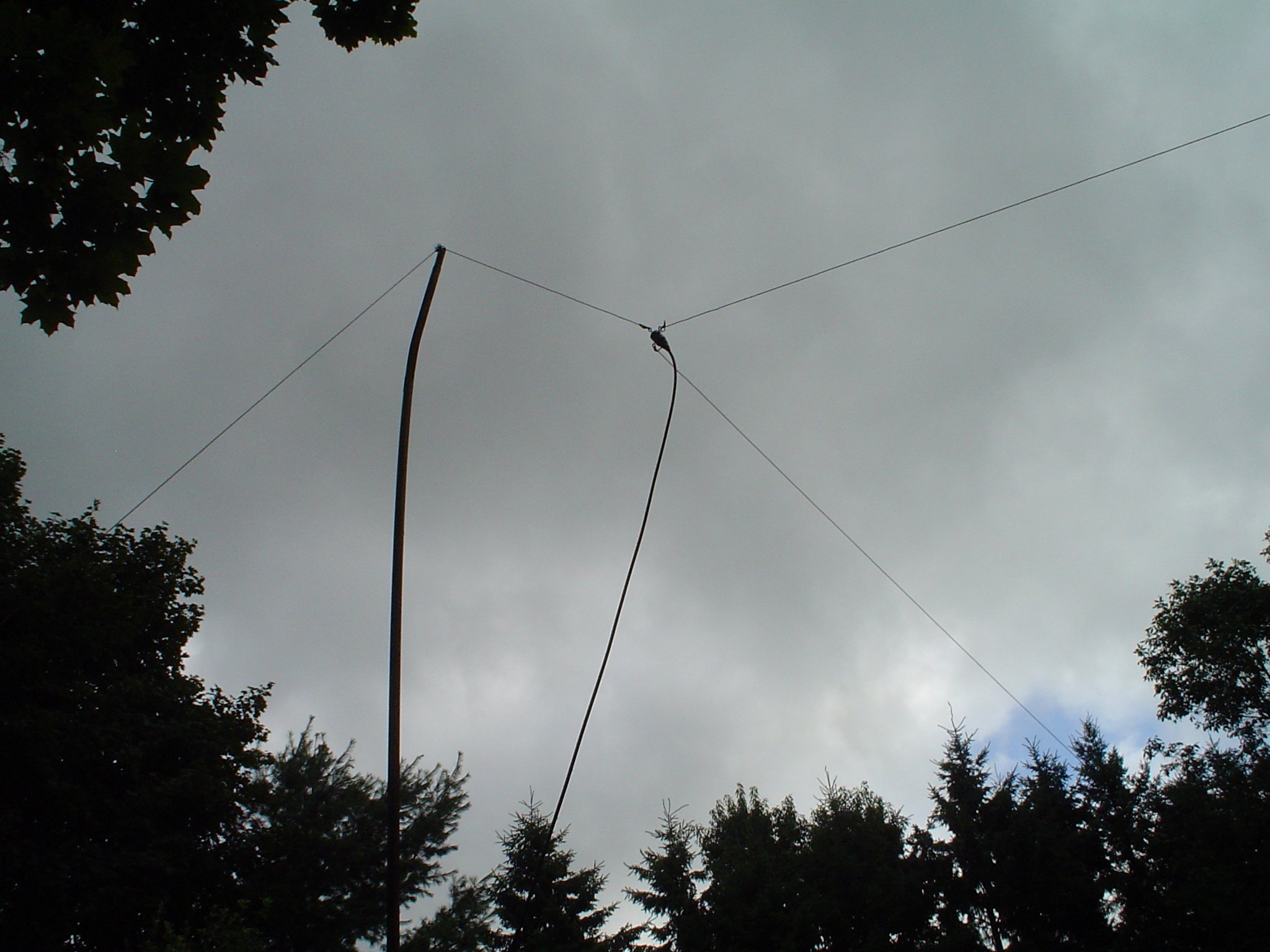
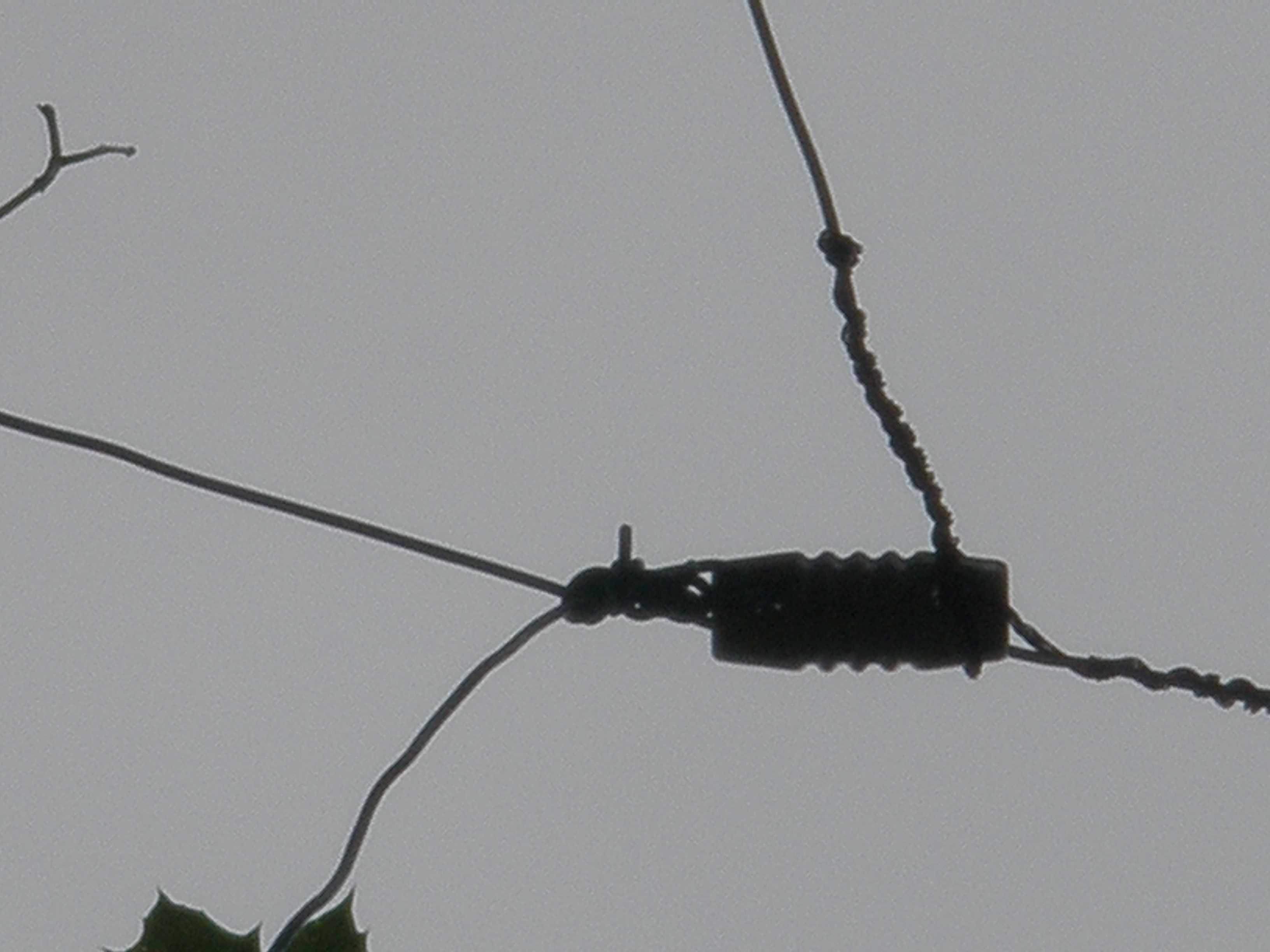
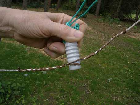
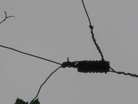
I used ceramic MFJ 16C06 insulators in Ithaca. I now have a linear amp that covers 160. Use a bare wire to hold the insulator in position on the insulated antenna wire as shown. A wrap through the hole doubles back the bare wire, so that it will not slip. The Ithaca antenna has been raised to approximately 30 feet or more. I have not yet had time to characterize its performance compared to the 10 to 15 foot level.
For heights of 10-20 Feet, a loop will substantially outperform a low dipole or anything else
at the same height. Under good
band conditions, I have worked the west coast of the USA on 160 meters with 100
Watts on CW, presumably on multihop using a 15 ft height. I think I might be able to do Europe on multihop over the Atlantic ocean
this winter with the new 35 ft height. But it is NOT a vertical over a good ground for DX, so
don't count on it. I was able to raise my Ithaca antenna to 30 feet or more in June of 2017. I will post any observations on improvement later.
I use a $13 Wireman #801 CQ dipole center insulator: 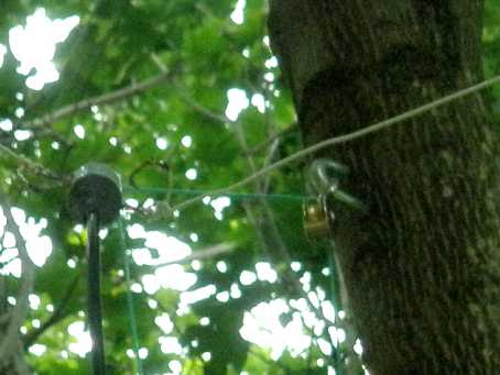
I use ceramic MFJ 16C06 insulators at each support. You probably can use the cheap plastic ones at 100 watts for a while, but I have a linear now, and the cost difference is just not worth the risk of arcing. Use the best stuff and install it ONCE.
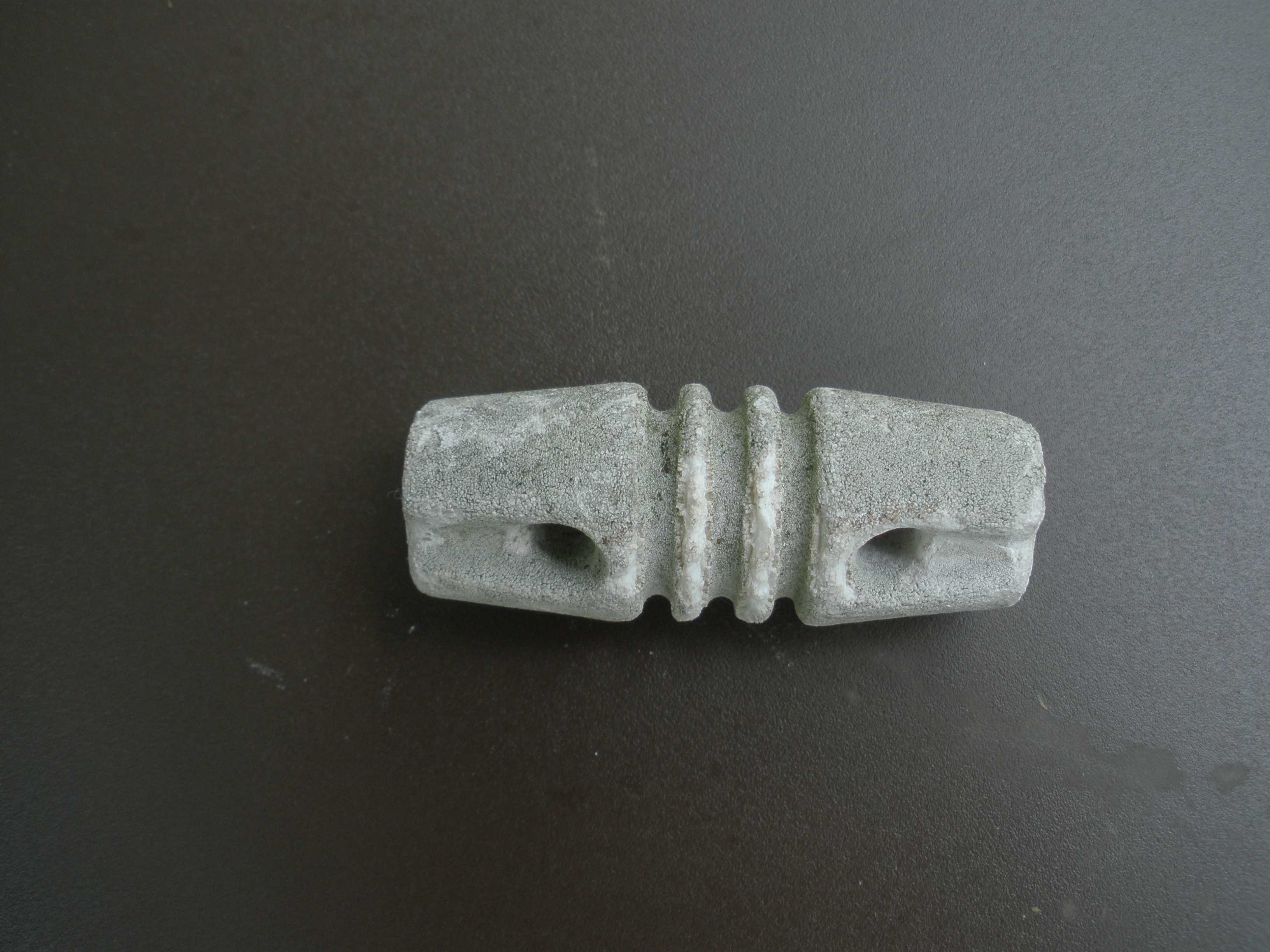
I do not understand why people will "save" less than a buck and install these lousy plastic insulators, in a long term antenna installation. For a short term throw away antenna, or a portable antenna where weight is significant, maybe. Here are actual photos of plastic insulators taken down after 5 years on Long Island. These were not exposed to salt water, but it is damp there, and there was a lot of sun. The surface has deteriorated and eroded, exposing rough interior plastic. It is incapable of shedding water, but rather traps it. Significant amounts of power would break it down if it got damp, and even at QRP the loss would make it unuseable. If you have any of these in your junk box or on existing antennas, throw them the heck out and get some decent ceramic insulators. Click on the photos below for enlargement.
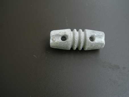
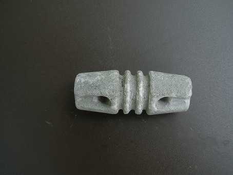
Some high priced commercial antennas come with these crappy plastic insulators. Take them off and throw them away immediately after you take these antennas out of their box. Replace them with MFJ 16C06 insulators or better. At swap meets, buy up older ceramic insulators whenever you can. I do not understand why people study for an exam and learn the formulas for antenna lengths, obtain SWR bridges or antenna analyzers, and still buy pre cut commecial dipoles. The purveyors of these antennas have to compete on price, so they often take short cuts. In the case of commercial multiband fan dipoles, nearly all have separator insulators that are too close spaced. The manufacturers make the assumption that the average ham does not know how to operate a calculator, a 100 foot tape measure and wire cutters; I hope they are wrong. Do not be afraid to use the design tools you learned from your club's radio instructor who prepared you for your exam. Commercial dipole antennas do not possess a secret blessing from some mysterious incantation that imparts 8 dB of extra gain in all directions over your own home brew antenna! (Hint, drum sounding in background: The secret incantation is: "O-wah Ta-nu Bi-yam" - chant it at increasing speed until you reach enlightenment, grasshopper.) Please take this in the spirit in which it is offered: not the grumblings of an old curmudgeon, but the encouragement to "exper"-iment and gain "exper"-ience that gives you the confidence to build your own antennas from high quality available raw materials and learn something useful in the process.
In Ithaca, the rectangular loop measures 100 ft by 150 ft, with no balun; a quarter wave length matching section of DX Engineering RG-11/U 75 ohm coax of 103 ft reduces the approximate 100 ohms antenna impedance to 50 ohms. The formula for this impedance transformation was on your Extra theory test. For a discussion of how this technique works, see:
https://en.wikipedia.org/wiki/Quarter-wave_impedance_transformer.
DX Engineering sells RG-11/U in bulk:
https://www.dxengineering.com/search/product-line/dx-engineering-rg-11-u-75-ohm-bulk-coaxial-cable.
The quarter wave line theoretical length is:
Length = 246 × Velocity factor / F (MHz) = 246 × 0.86 / 1.9 = 211.56 / 1.9 = 111.3 ft
The direct measurement method I used with the MFJ259 analyzer came up with approximately 104 feet for slightly above 1.9 MHz. The increased resistance in the SWR plot at the low end of the band shows that choice. The matching section is a TUNED feeder effective over a narrow frequency range.
| The quarter wave impedance transformation formula is: |
| Zload = (Z0)² / Zin |
|---|
| Zload = 75² / 50 = 5625 / 50 = 112.5 ohms |
|---|
| antenna impedance,
which is about right for this height. |
The MFJ-259 antenna analyzer manual tells you how to measure a quarter wavelength coax line. If you use the line specified, my length should be close enough to work, if you cut the antenna length properly. There is negligible loss in this 75 ohm section as it operates at only 1.5:1 SWR. Then another approximately 100 Ft of standard 50 ohm coax brings it into the shack. This is optimum total length, a half wave, so that the transmitter sees the impedance at the antenna, not something colored by the length of the transmission line. Any excess line can be coiled up, or you can use the 75 ohm coax for a choke balun by coiling it up near the feed point. The graph shows the SWR and impedances. Note that the SWR minimum and zero reactance coincide at 1.905 MHz. 160 meters is one of the most challenging bands, since the roughly 200 KHz bandwidth is about 10% of the frequency of 2 MHz. Similarly, on 80 meters, 500 KHz is more than 10% of 4 MHz. A loop is inherently wider bandwidth than a comparable dipole. In any event, the internal tuner of any modern rig is capable of matching the 160 loop, when fed this way. My FT-950 matched it perfectly with its internal tuner. Note that this is not a highly reactive high impedance load of 10:1 or more, such as a G5RV, and does not stress a tuner even when running full legal limit. I recommend the ceramic antenna insulators if you run over 100 watts.
 For low heights, a 75 meter loop also is a good choice, if you cannot
erect a higher dipole. I took down my 75 meter loop to make room for
the high dipole described in my other article.
BUILD AND ADJUST YOUR LOOP TO CORRECT LENGTH FOR BEST SWR IN JUST ONE HOISTING
Click here to use the Calculators for Making your Own Wire Antenna written by Don, AC2RS.
The following procedure works for full wave loops, half wave dipoles, and quarter wave verticals:
- First, if you haven't already done so, cut your own dipole wires to slightly longer than that required by the lowest frequency in the band of interest using the first calculator on Don's page.
- Then, measure the actual frequency of minimum SWR (and zero reactance if you have an MFJ antenna analyzer).
- Plug those numbers into the second calculator to find out how much to adjust the length.
- Let your antenna down JUST ONCE (if it was up yet), adjust the length, put it (back) up, and you are done!
The third calculator on Don's page is a tool for determining correct length of a quarter wave transmission line of 75 ohm coax (RG-11/U from DX Engineering) to transform the 150 ohm nominal full wave loop impedance to 50 ohms for tunerless fun. This tool can also be used to calculate the right length of 75 ohm line to transform the third harmonic operation of a 40 meter dipole for 15 meters. The short length of match section in that case would have minimal effect on the 40 meter operation. I have done this, and it works! The hats or stubs added at approximately 11 feet out from feedpoint can also shift the resonance lower in the 15 meter band without influencing the 40 meter resonance.
HOW TO FEED A LOOP DIRECTLY AS I DID WHILE ON LONG ISLAND
On Long Island, I am able to bring the wire directly into the shack and
feed it from the tuner, in early times, a Ten Tec 291. I upgraded to a Dentron MT2000 when I obtained a SB-200 linear for 80 meters and up. This Dentron MT2000 is one of the few tuners which actually specifies the loss at match: less than 0.5 dB. I do NOT use the tuner's internal balun to avoid
losses inherent in such operation. Most all tuners use an inferior voltage balun, and should never be used. If you feel you must use a balun, get a good external CURRENT balun rated for the power and frequency you need. I directly grounded one side of the loop. I feed
the other wire of the loop from the coax connector. Balance does not
matter. Getting the most RF in the air matters. Only use a balun when it is
indicated. Some guy telling you that you oughta have a balun is not an
indication.
On Long Island, no coax or feeder of any kind is used. One side of the antenna goes directly
to a ground stake, for lightning protection. A ground wire to the grounding screw on the
pass through panel by MFJ in the double hung window completes one
side of the loop. The other side goes to the center of a coax
connector on the MFJ panel. Impedance is about 150 ohms RESISTIVE. Since the antenna is resonant, there is little reactance and no high voltages. The antenna connects
via a short piece of coax inside the house to my antenna switch and
tuner.
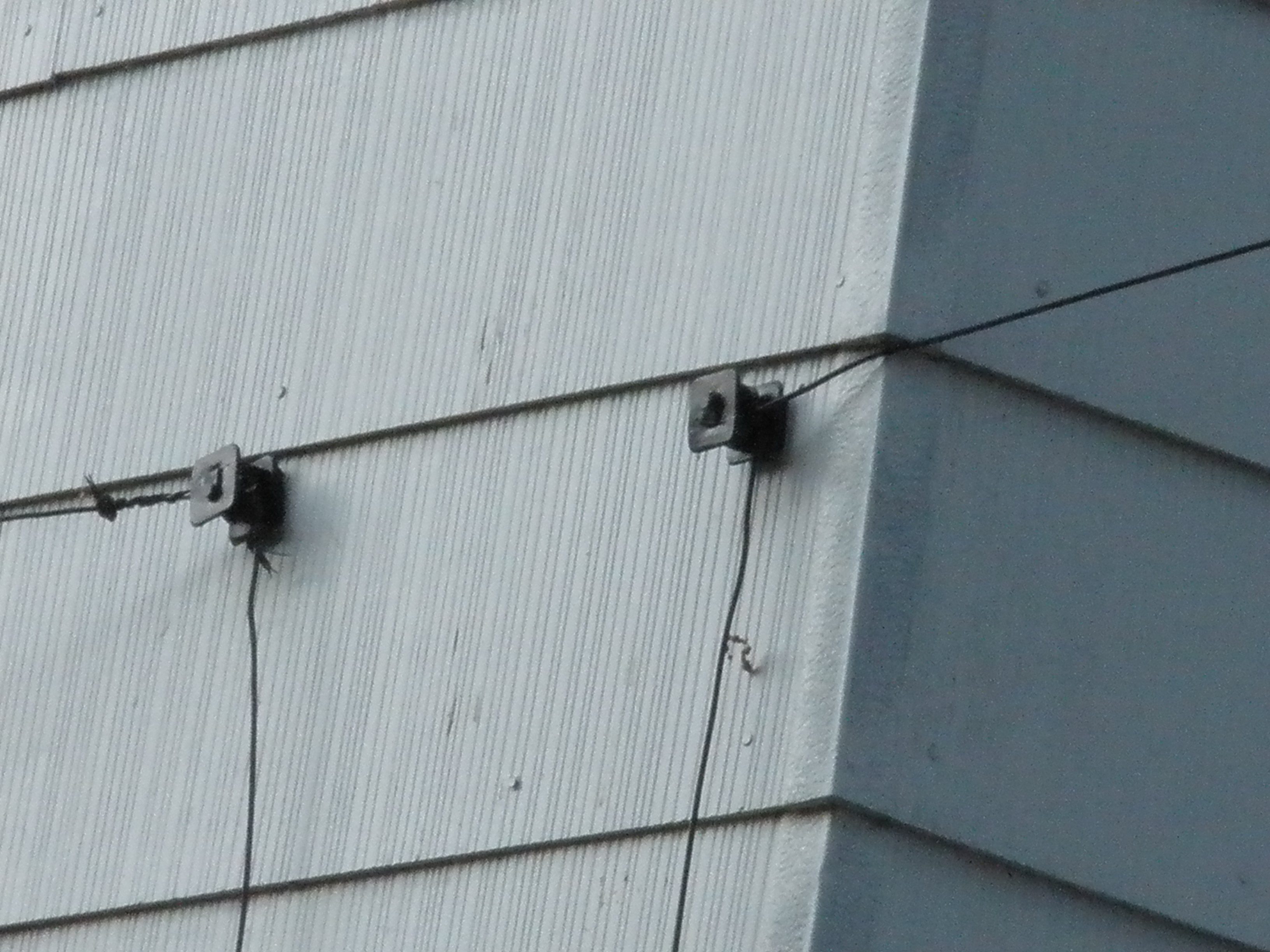
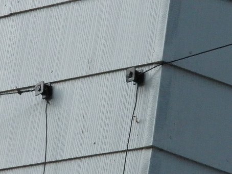
The insulators on Long Island are available at Agway or a farm store. They are electric
fence insulators. Cheap plastic insulators work just fine, since the
loop is a low impedance device and I do not exceed 100 watts. As a plus, it will
keep your giraffe herd safe at home. After all, it can be made with electric fence wire and insulators.
My electric fence antenna runs from tree to tree, using the same electric fence insulators, about ten feet off the ground, in a rectangle roughly 100 feet
by 125 feet, on Long Island. The vertical wires shown in the photos are not open wire feeders; they make up the rest of the antenna length. I do not do open wire feeders, for a variety of reasons already discussed on this page.
|