|
The Ameritron AL-811H is an attractive choice as an entry level amplifier for the low budget amateur operator. The modern components are rated to deliver reliable, effective HF communications power levels if operated within their specifications. The AL-811H has the essential design elements for a clean, stable signal. The lowest priced amplifier, the three tube AL-811, lacks neutralization and some other important design features that are included in the AL-811H. I would encourage you to spend the extra money to get the AL-811H instead of the 3 tube model, if those were your options.
There are certain design measures in the W8JI updates that protect the amplifier from damage if arcs occur. There are also reports on eham reviews of receiver front end destruction due to tube arcs getting back to the transceiver. This amp is not the only grounded grid tube amp that needs this protection; it has become a problem, due to inferior tubes of today. If you have an older model AL-811H which does not have these design updates, I urge you to install them, or send the amp back to Ameritron for rework to current specs. This web page is a detailed step by step supplement to the W8JI instructions. I also install an arc protect fuse and resistor in the HV lead. This measure is standard in Ameritron higher priced amplifiers, and a common mod to update older amps like the Heathkit SB-200. I installed similar modifications on my SB-200.
Installation of the 200 ohm swamping resistor is "optional", according to the W8JI instructions. I put it in, after we encountered a clicking noise in the receiver in amplifier standby mode. The 200 ohm resistor does not have a DC path to the cathode circuit, so I did not understand how it would improve the cut off bias situation. The only purpose I could see it serving was to terminate the input circuit by resistive loading, to reduce a tendency to break into a burst of RF oscillation due to the tubes not being properly biased OFF. The burst of oscillation is very brief, and no current is indicated on the plate meter. It automatically extinguishes when the arc suppressors fire, upsetting the bias. W8JI states that in some cases the clicking happens on different bands with varying plate and loading settings. This is the classic definition of instability. Otherwise, the plate and load or band settings would be irrelevant. It is not surprising, since if the tubes exhibit sufficient gain, and there are no resistive terminations on either the input or the output, oscillation may occur, even in a well designed amp. In the standby mode, neither the input nor the output of the amplifier are terminated, and the plate supply voltage is ON. If the tubes are not actively driven into cut off (no gain) the amplifier, even though it is neutralized, will possibly oscillate even though it is neutralized. Under normal conditions with the relay closed, the tubes are connected to a transceiver on the input and an antenna on the output, and it is stable.
The 200 ohm resistor did not cure the clicking problem in our case. It is supposed to prevent a clicking noise in the receiver while in standby; that may or may not work for you. The schematics in the most recent releases on the Ameritron web site do not show either this mod, or the other W8JI mod (which I did not try) which uses a DC bias derived from the High Voltage supply to drive the tubes into cutoff (no plate current). The gas tubes fire at 150 VDC, which accompanies the clicking noise. The bias in the W8JI high voltage resistor bias mod is a bit above 50 VDC, but 150 VDC is apparently not sufficient to cut off the tubes. Otherwise, I speculate that residual gas in the tubes is driving the cathode voltage above that cut off voltage value (otherwise the arc suppressors would not fire). Since neither of the mods W8JI suggested are installed in current production models, I did not proceed further. Apparently they select tubes for proper operation in their amps, since eham reviews does not note this problem.
The new tubes used in the rebuild worked fine otherwise, but they were not from RF Parts or Ameritron. Possibly your results will be better, if you use tubes from those suppliers. I cannot imagine users of new AL-811H amplifiers not complaining about the clicking, so Ameritron must select the tubes for cut off characteristics as well as burning them in to reduce the arcing problem with new Chinese tubes. The W8JI 200 ohm resistor mod increases the drive power from about 40 watts to 45 watts on 80, 40, and 20 meters. Installing a pair of 200 ohm resistors requires redesign of the input matching network, as W8JI notes. Other bands are proportionate in drive demands. You must avoid drilling a mounting hole that damages the neutralizing transformer. You must be careful to avoid pinching the wires from the filament choke under one of the standoffs when reinstalling the sub chassis. Adding a B+ fuse and protection resistor is important, and NOT covered in the W8JI mods. There are other details, but first you must have the W8JI instructions. Go to the W8JI page and print these pages out:
https://www.w8ji.com/al811_important_modifications_changes.htm
https://www.w8ji.com/al811_update.htm
Then you are going to have to order some parts. Here is the list of parts and sources to order, with approximate prices:
RECOMMENDED SET OF FOUR GENUINE 811A TUBES, 100% TESTED AND GUARANTEED CETRON: $56 X 4 = $224
https://www.rfparts.com/tubes/tubes-811a.html?p=1
OR (See discussion of W8JI on power rating of Chinese tubes more like non-A old 811s)
Ameritron 811A Replacement Power Tubes #380-0811A $30 X 4 = $120
AMERITRON PARTS:
GAS TUBE, SURGE ARRESTER, 150V: #304-6015 (QTY: TWO) ABOUT $2 EACH
HV ARC RESISTOR, 10 OHM 5% RCD 175P: #110-1100-1 (QTY: TWO) ABOUT $3.36 EACH
IMPORTANT: Do not substitute on the 175P style resistor. This is designed differently than a standard resistor, and will handle a surge current properly, without exploding. That is why Ameritron puts them in their bigger amps. I got this part from one of those Ameritron parts lists. It is not standard on the economy amps in the AL-811 series.
SUBASSEMBLY, PCB, PARASITIC CHOKES AND PLATE CAPS: 50-0572-1 ABOUT $37.62
PROBABLY YOUR RESISTORS ARE FRIED, AND THIS IS FOR BEST STABILITY WITH MODERN TUBES.
REPLACEMENT FAN, IF YOURS IS NOISY: #410-3583 ABOUT $18.85 EACH
USE A DIFFERENT BIGGER FAN AND MODIFY CABINET IF GOING TO 572Bs, see note later
CAPACITOR, ELECTROLYTIC, 270 uF 450V #270-6210-7 $13.53 EACH (FOUR REQUIRED) $54.12
NOTE: There is a lot of internet hype about parasitic suppressor design. I favor using the parts Ameritron and the designer, W8JI, recommend. They produce a lot of these amps. A ham without the engineering level test equipment who comes along afterwards with a speculative parasitic suppressor circuit design that works on one amplifier leaves me uneasy. The Ameritron PC board listed above is an easy install with no questions about stability.
MOUSER PARTS:
200 OHM 20 WATT RESISTOR, NONINDUCTIVE: MOUSER P/N: 652-PWR-221T-30-2000F ABOUT $2.64 EACH
MISC PARTS MAYBE IN YOUR JUNK BOX:
SCRAP OF BARE G-10 PC BOARD MATERIAL OR OTHER INSULATOR TO MOUNT THE FUSE
FUSE HOLDER, CLIP TYPE:
FUSE: 1 amp fast, be sure to use 250 volt type. Do not use smaller metric style fuse.
TOTAL COST OF REBUILD AND UPDATE: $72.47 for small parts, + capacitors $54.12 + $120 TUBES = $246.59, or more like $367 if you get the RF Parts 100% tested and burned in Cetron tubes. This does not include labor, if you had to hire the work done.
SO IF YOU PAID ABOUT $800, you broke even for a used amplifier with no warranty, not counting your time to install the new parts. This assumes you did not uncover other problems during the rebuild. For instance, you may have to replace D16 and other components damaged from tube arcs. This is why I recommend people new to amateur radio just buy a new amp with a warranty. If you already own an AL-811H, it is worth the cost of parts to rebuild it and bring it up to current factory specs, if the amp suits your needs.
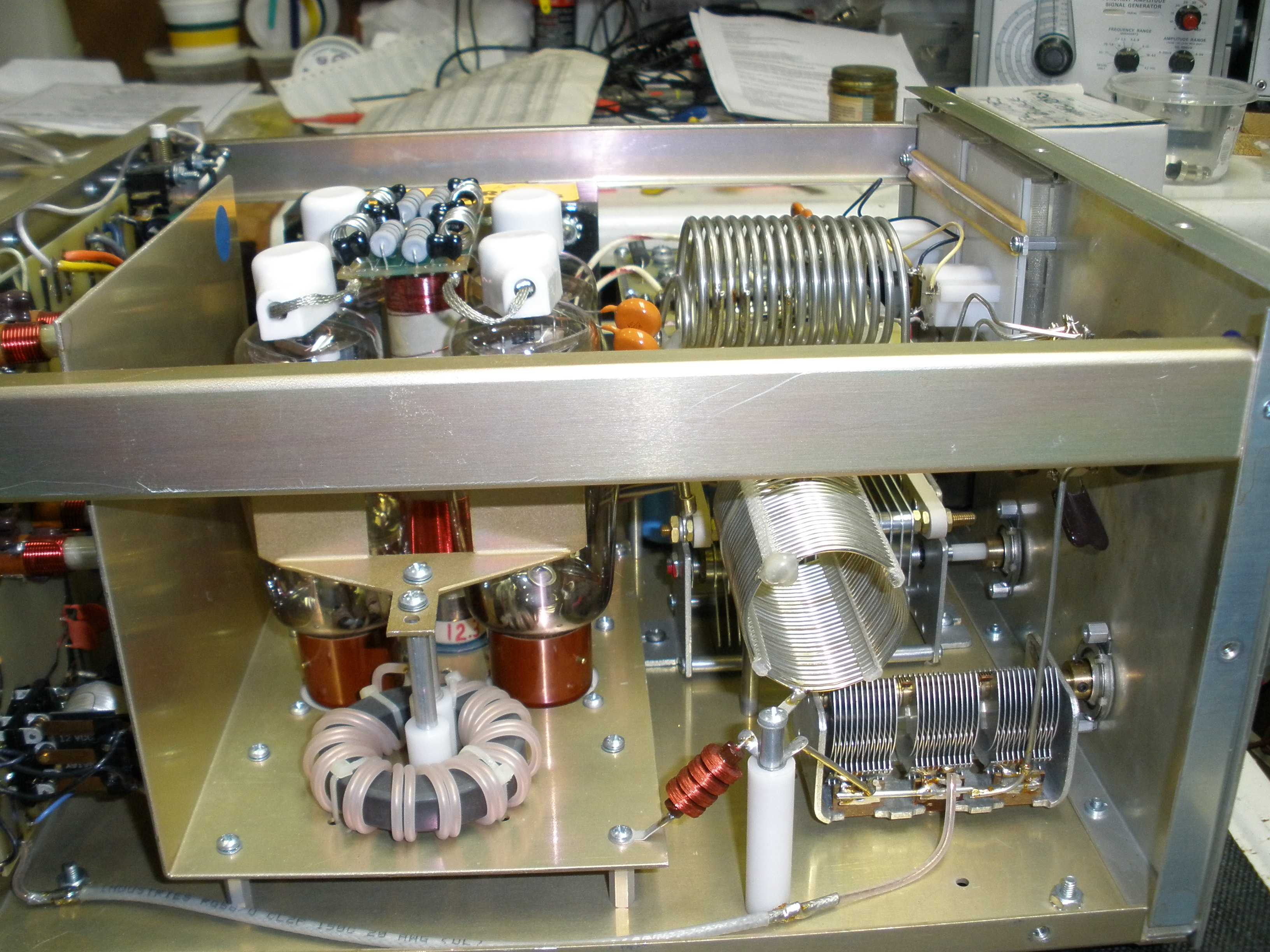
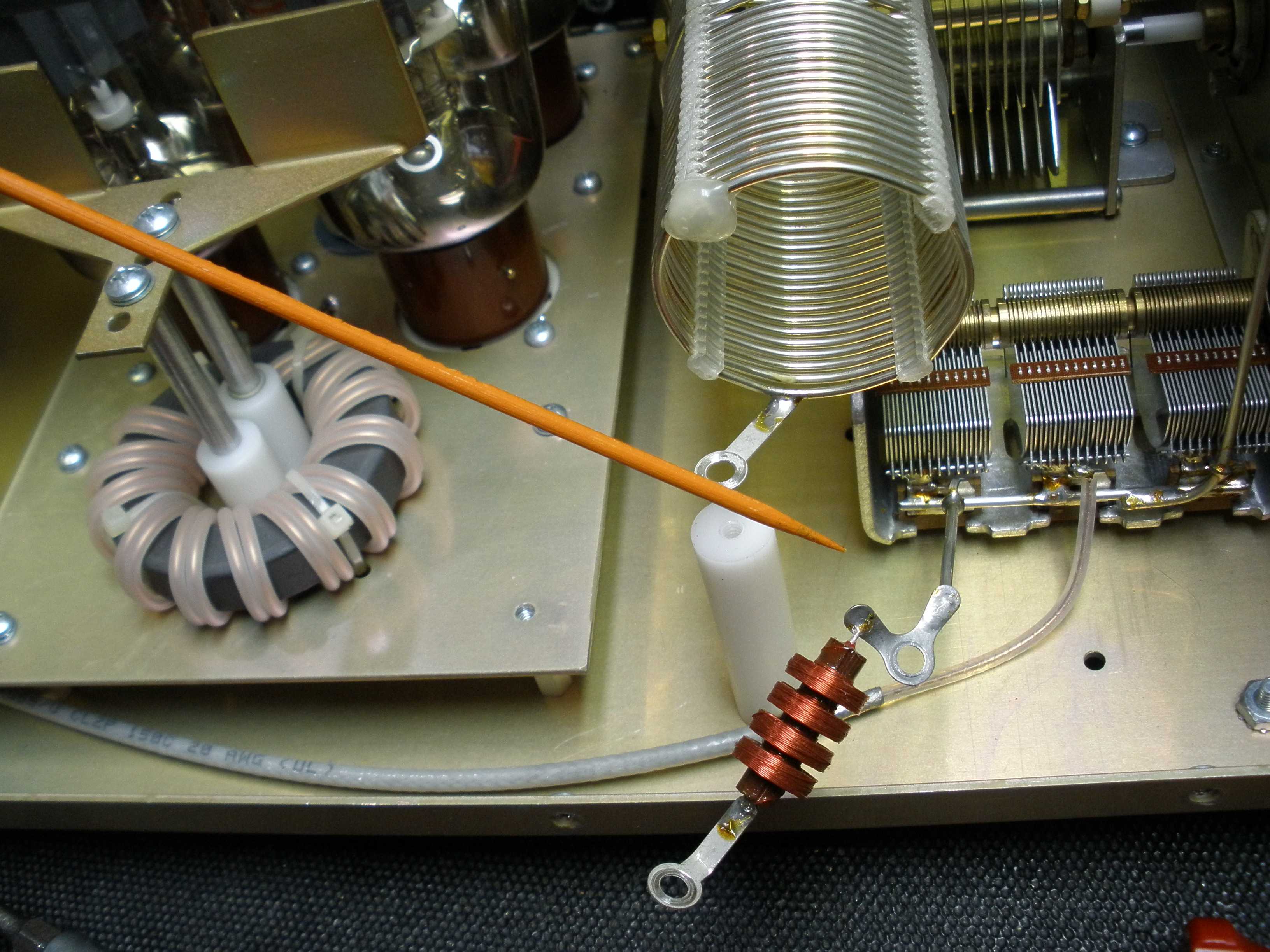
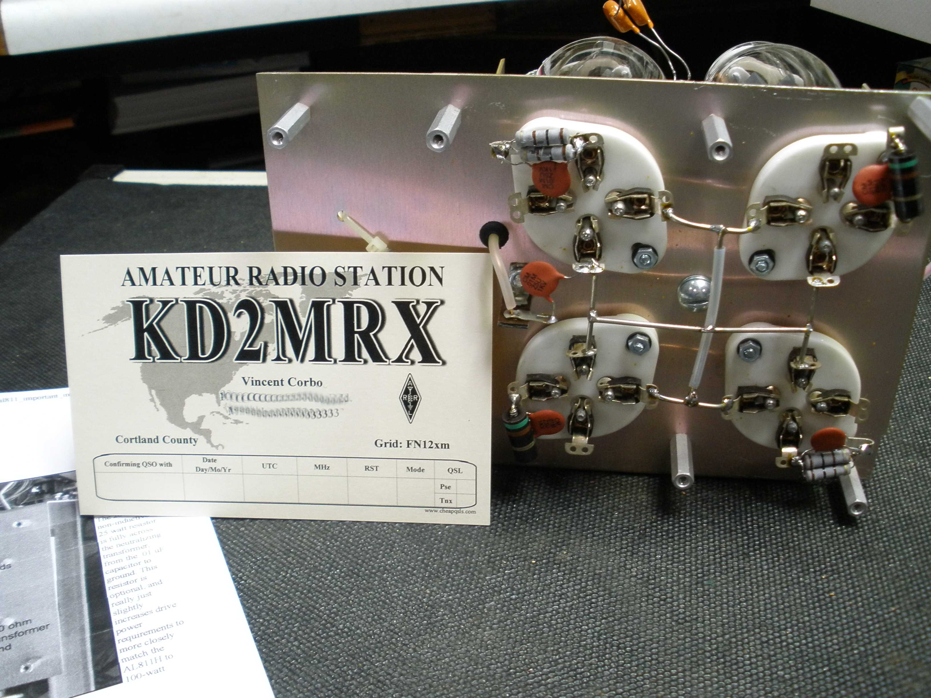
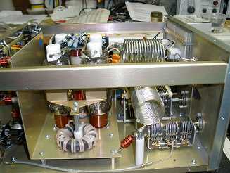
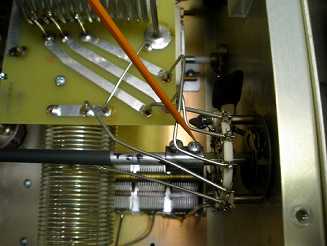
So now you have your parts and the W8JI pages above printed out. Let's get started. First thing I do before work is to take photos of the rig, so I can get it back together correctly. Click on any photo on this page to enlarge it. Note particularly the way the spacer and RF safety choke are assembled, and where the orange ceramic plate blocking condensers connect.
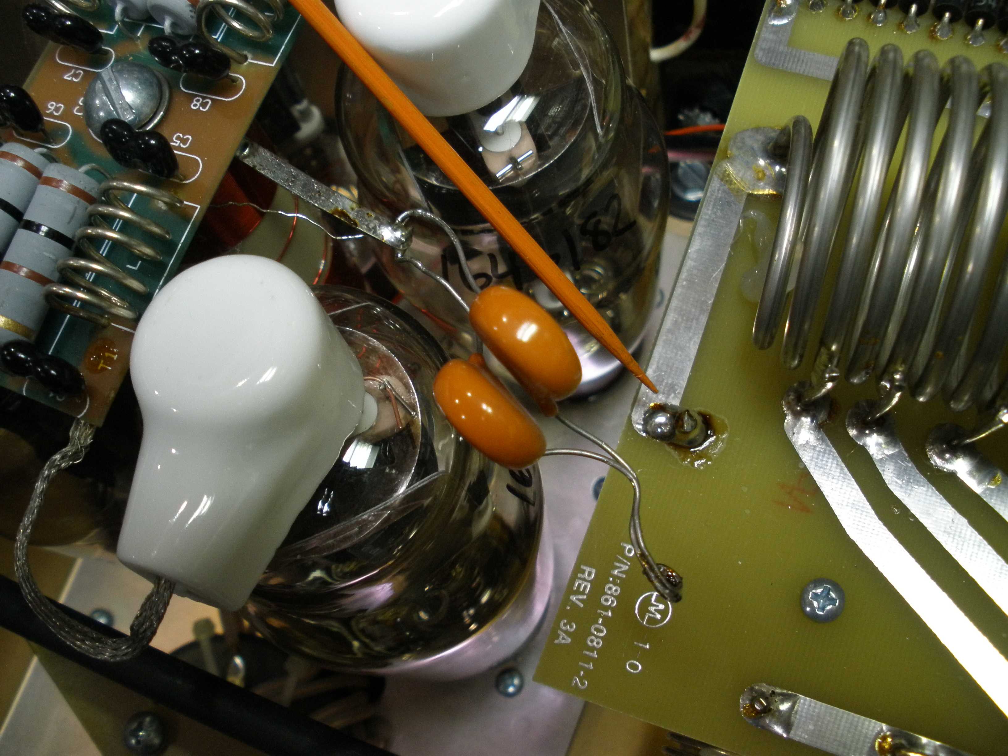
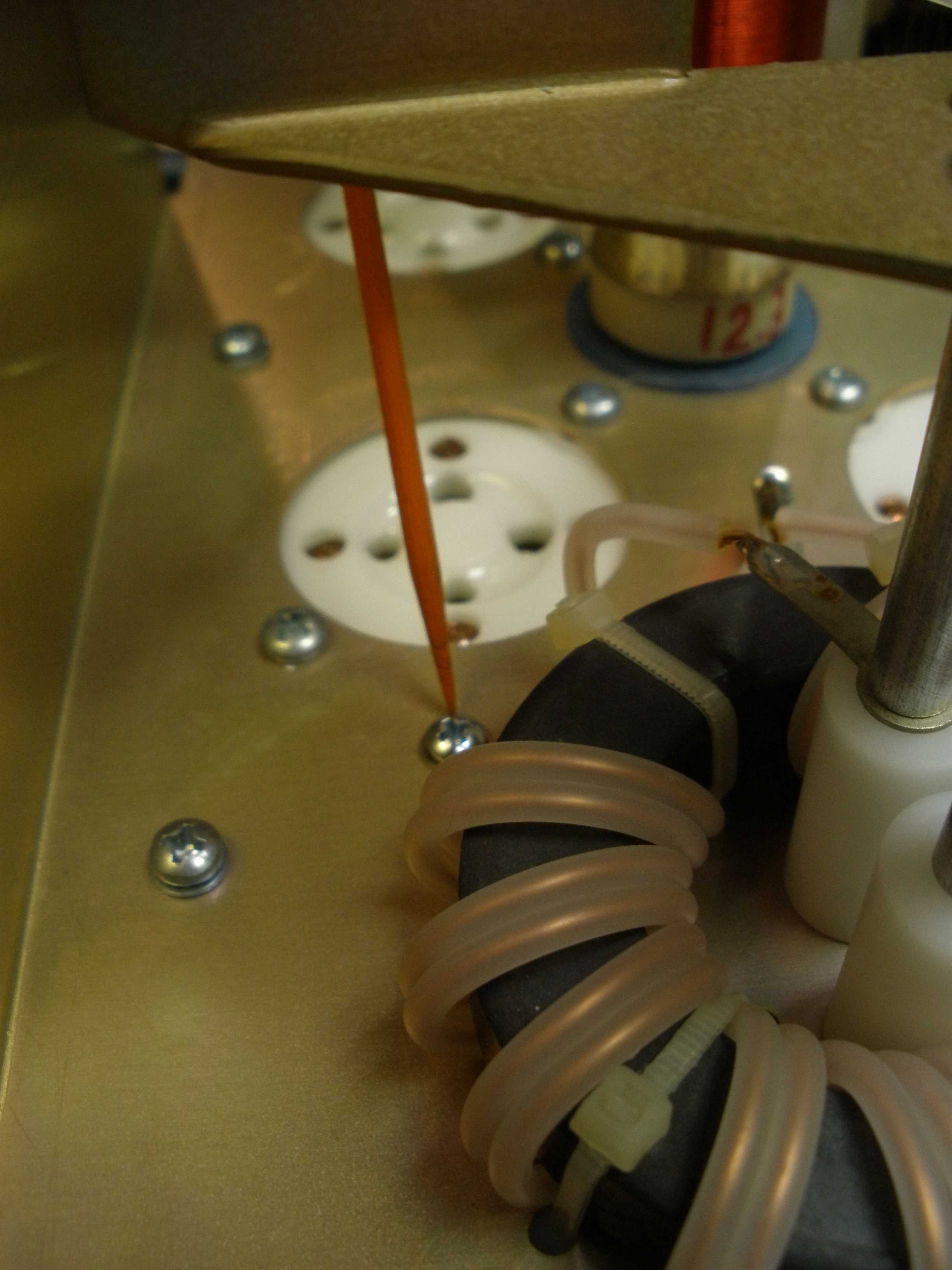
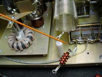
W8JI first removes the side bar between the front and rear panel. I have a small container with a lid to save all the screws removed, so they do not get lost. Then W8JI disconnects the orange ceramic disc plate blocking condensers. See the orange pointer showing solder joint. Do not splash solder, damage the plate choke and neutralizing assembly, or do anything else silly. Loose screws, solder splashes, and metal drill shavings will fall places that cause the maximum damage. This is known as the Law of Selective Gravitation, discovered by the author Charles Shultz, and explained by Charlie Brown in the Corollary: "The Jelly Bread Rule". The bread always falls jelly side down.

Then W8JI disconnects the RF choke that serves a safety function by grounding the output of the amplifier for DC in case certain components fail. Be careful of the fine wire. I did not unsolder it, I just swung it out of the way.
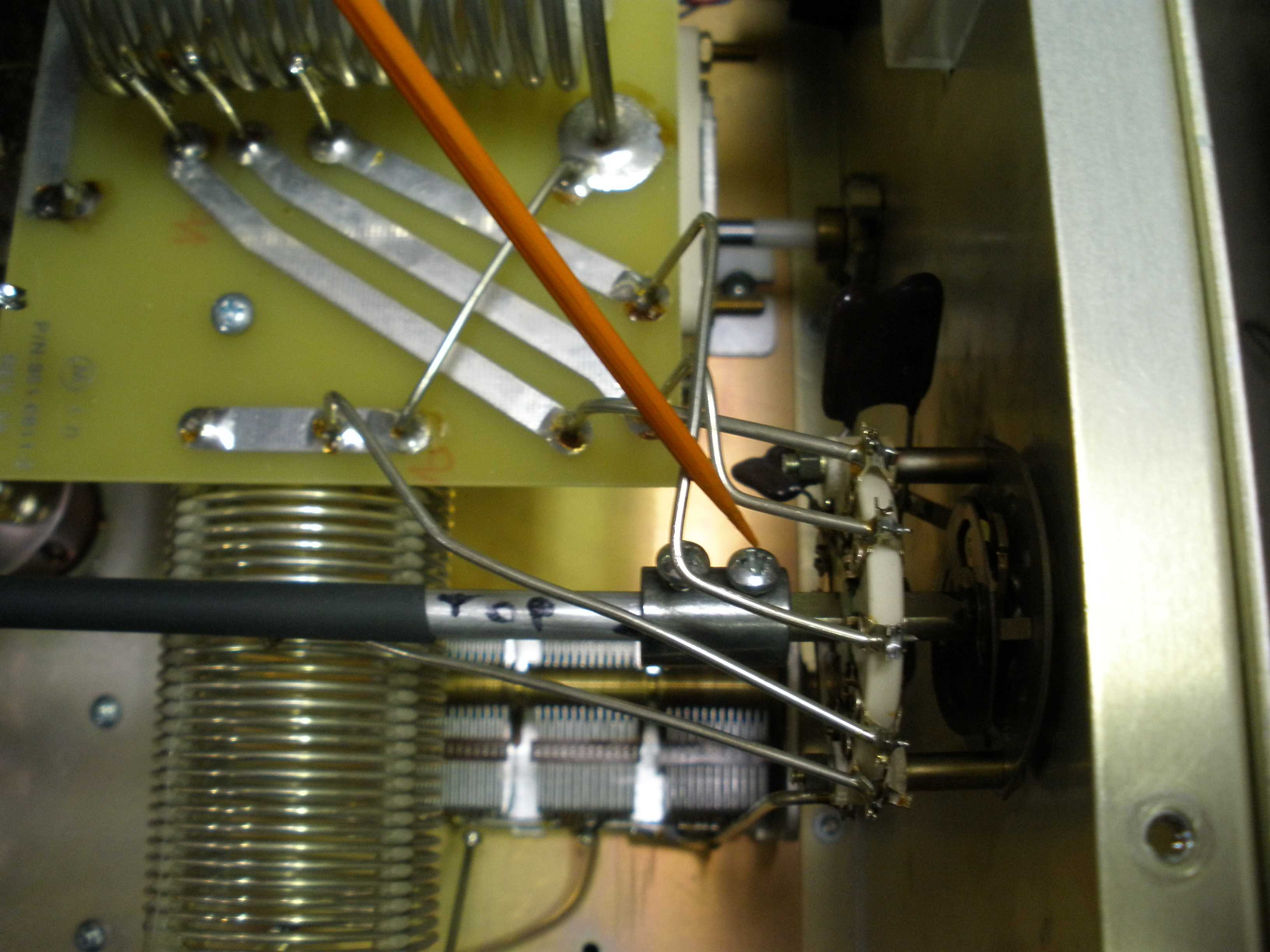
IMPORTANT: LOOSEN ONLY THE FRONT SCREW ON THE SHAFT COUPLING. This keeps the front and rear switch wafers on the same band, in sync. It is much better to avoid this, but there is a procedure to align them if you mess it up.
https://www.w8ji.com/al811_input_switch_alignment.htm
Follow the W8JI instructions carefully to disengage the front shaft coupling, while avoiding damage to the rear switch wafer. Replacing the switch wafer is very tedious. Once you have the shaft removed, the next step is to remove the tubes and set them aside for safe keeping. Then disconnect the red high voltage wire from the power supply PC board. W8JI does not include these steps, but the tubes are expensive. To install the 200 Ohm 20 Watt resistor, you have to drill a hole. You MUST mount the resistor to a piece of metal for a heat sink. That is much easier with the whole subchassis completely removed. The vibration from drilling can damage the tubes. The high voltage wire is fragile, and needs to be disconnected anyway to install the fuse and glitch resistor.
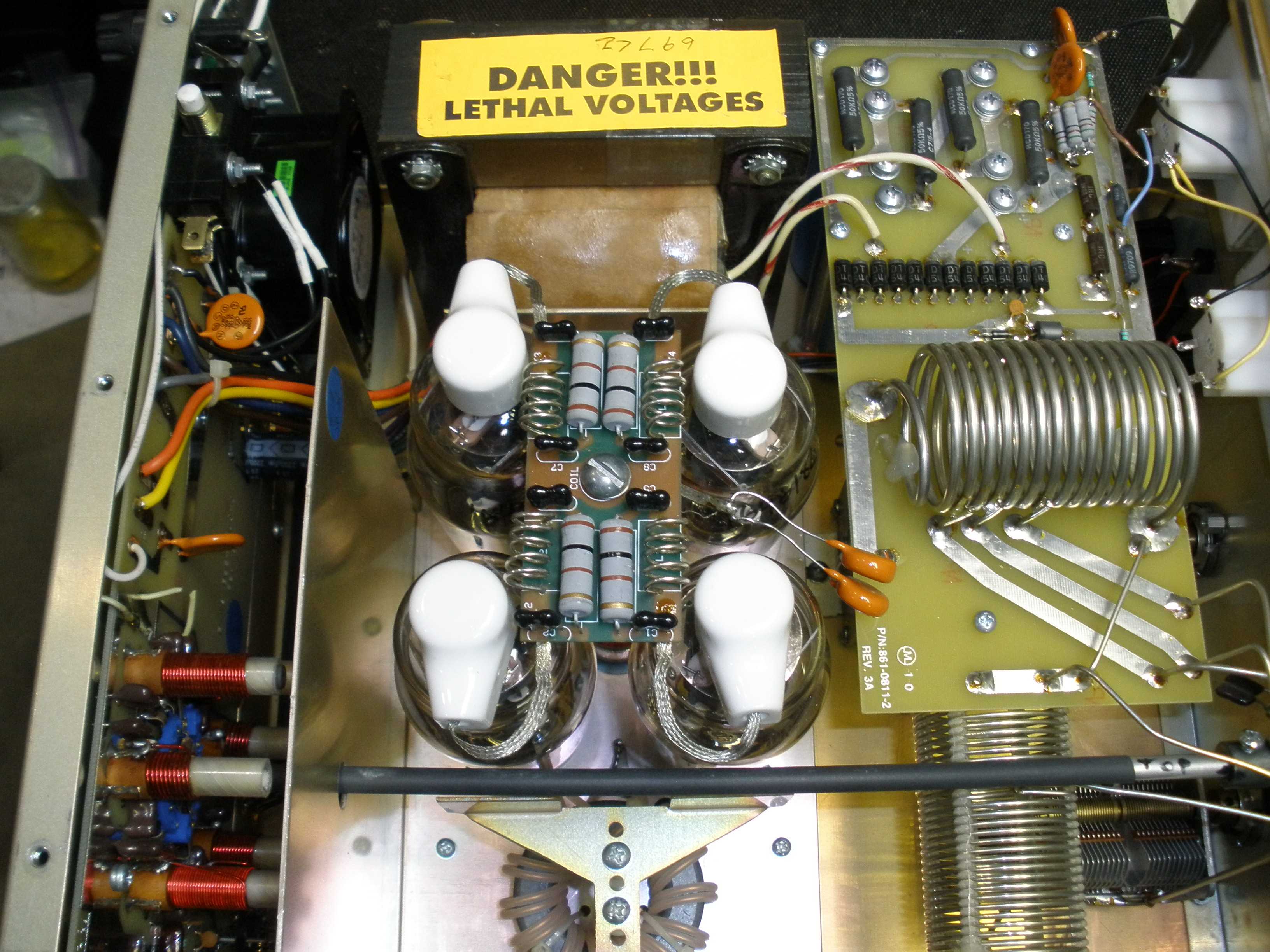
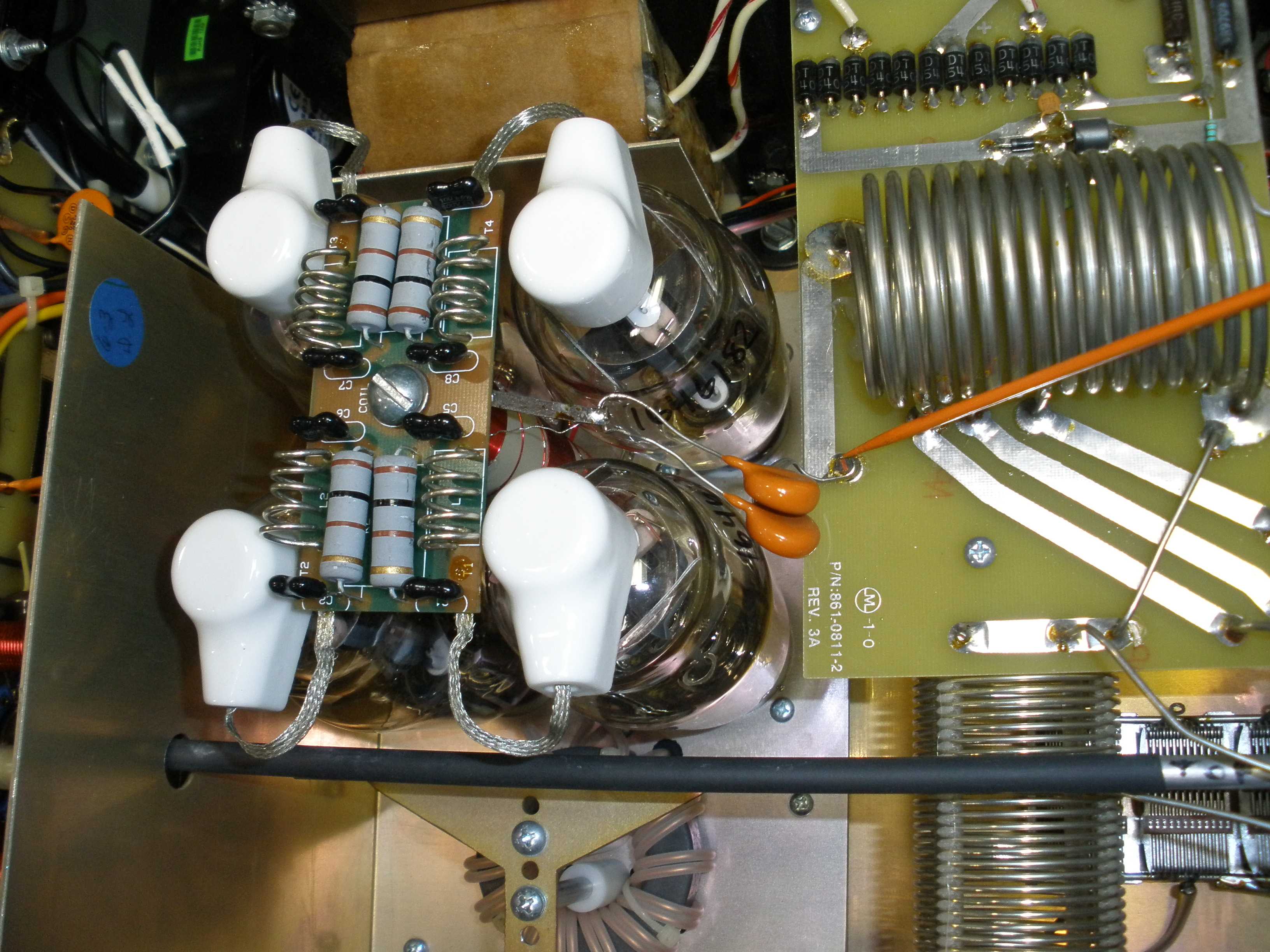
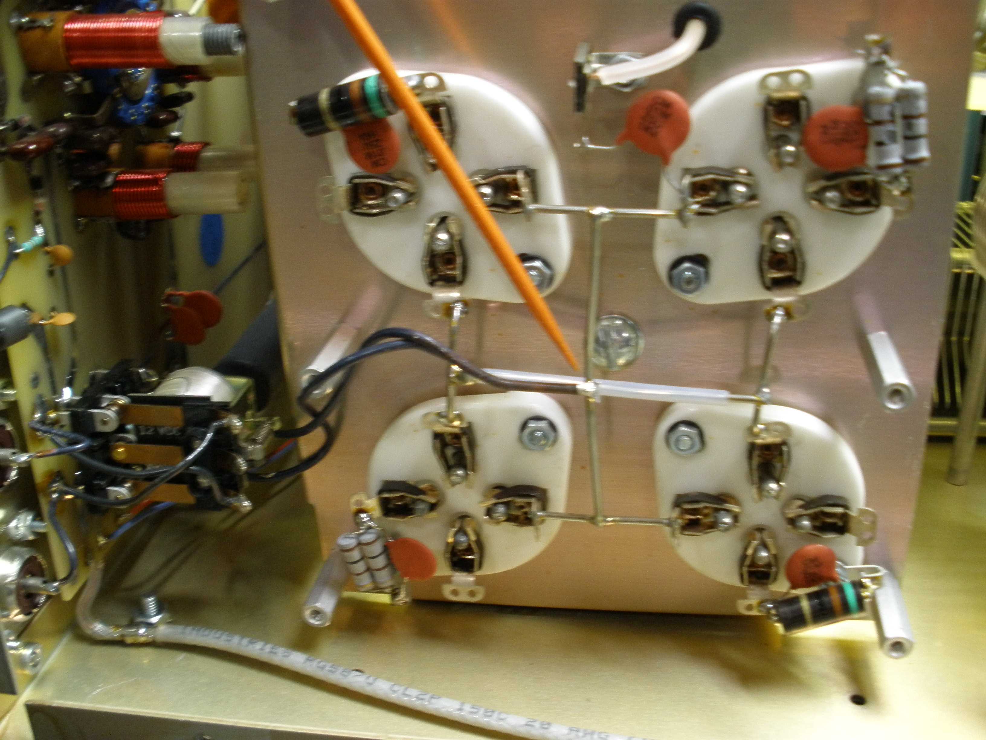
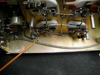
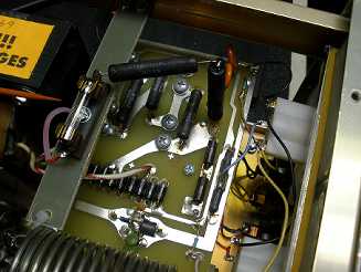
AFTER COMPLETING THOSE STEPS, remove the 8 screws from the bottom of the amp, as he shows in his photo. This allows you to carefully rotate the tube socket sub chassis, laying it down on the main chassis, as shown in this photo. I disconnected the filament wires to avoid abrasion or damage to the thin insulation coating on the wires. See the photos of the disconnection of the wires, as the orange pointer indicates.

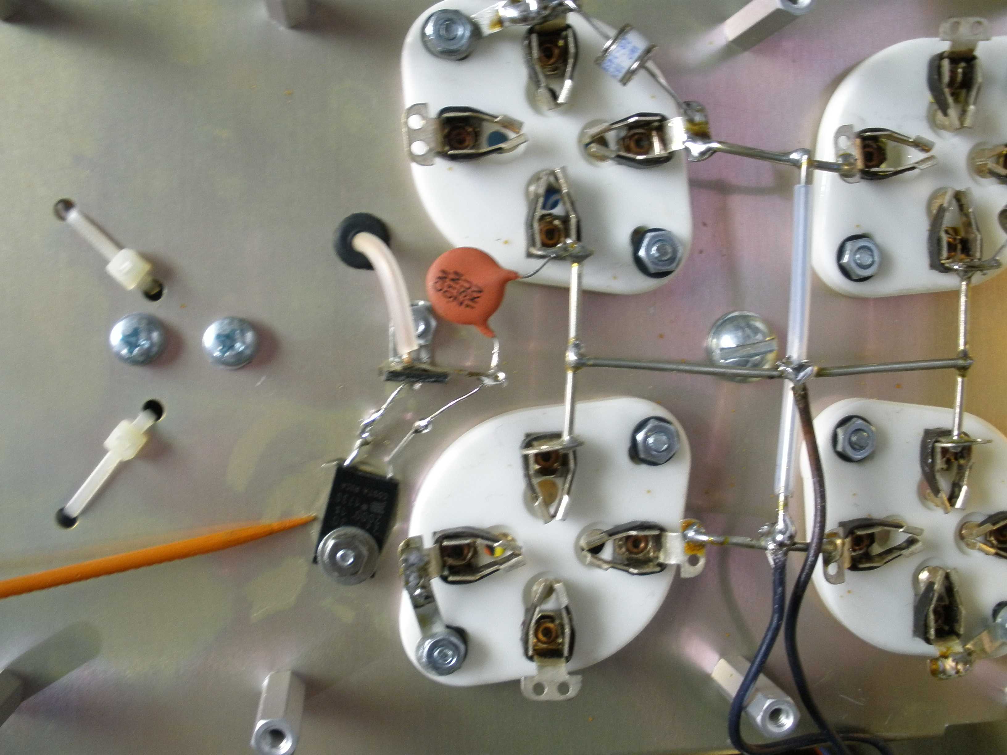
You can now see the resistors and capacitors from grid to ground used on the older AL-811H amplifiers. These often burned out if the tube arcs. Some of these were replaced by the seller with inductive resistors, explaining why the Parasitic Choke Resistors also burned out. You will need to remove those components and replace them with a ground lug that attaches to the mounting screw nearest the grid pin of the tube. Once you have installed the ground lugs properly in contact with the tube socket grid pin, solder the lug directly to the grid pin. W8JI arrows on his photo states: "Ground grids directly!" VERY IMPORTANT; DO NOT OVER TIGHTEN THE SCREW. THESE SOCKETS ARE CERAMIC AND MAY CRACK IF EXCESSIVE FORCE IS APPLIED. Also, this procedure is simpler than the one recommended by PA0RFI, which requires that you remove and rotate all tube sockets 180 degrees to get the grids pointing to the center, where he uses a wire to ground them at a central ground lug. This is a lot of work, and the sheet metal chassis is probably a better ground than a wire of any size.
Now that the grid resistors and capacitors are removed and replaced with a direct short to ground, we install the
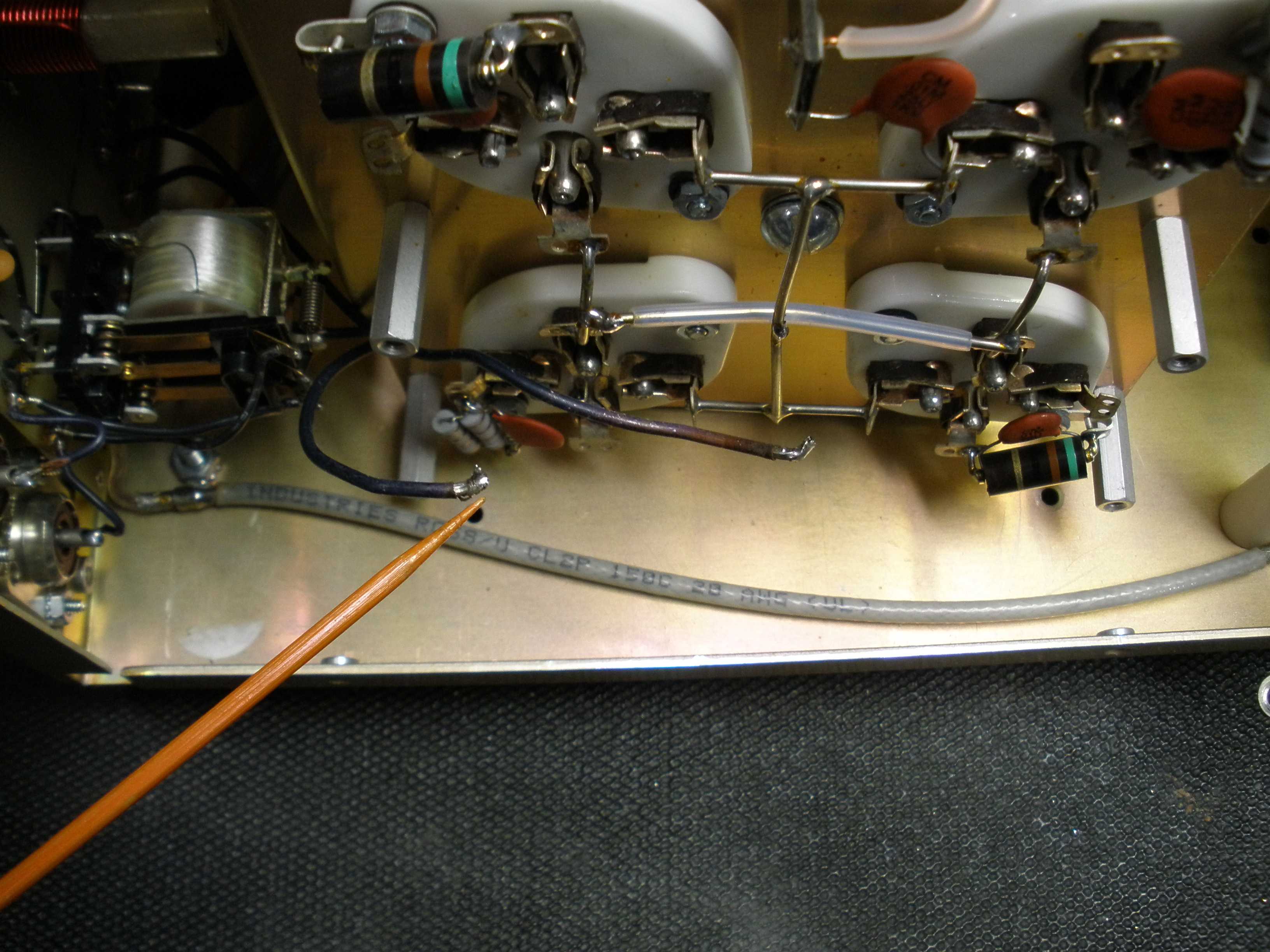
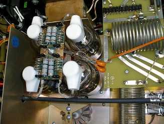
GAS TUBE, SURGE ARRESTER, 150V: #304-6015 (QTY: TWO) from each filament lead to ground. These normally do not conduct except in the case of an internal tube arc, which may occur in Chinese tubes. Connect them directly from a filament pin to ground, as shown in the W8JI photos as "Gas Arc Protect". You can see a close up of one of them, from the filament to the NEW grounding lug at the top of my photo. The second one is at the lower right, just out of view. Be sure you install one gas discharge arc suppressor on EACH filament lead, not two suppressors on ONE filament lead.

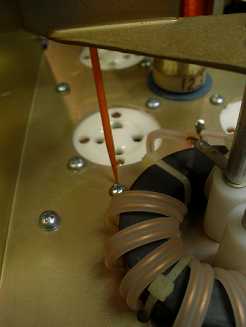
Now we install the Mouser 200 OHM 20 WATT RESISTOR, NONINDUCTIVE: MOUSER P/N: 652-PWR-221T-30-2000F. Drill a hole just large enough for a mounting screw. IMPORTANT: DRILL THE HOLE SO IT MISSES THE NEUTRALIZING COIL! I installed it differently from W8JI, because the terminal strip was mounted differently, and this resulted in the shortest lead length. USE HEAT SINK COMPOUND to couple the resistor to the tube sub chassis to maintain its 20 watt dissipation. Do not get rough with the leads, or there may be internal damage. I did this OUTSIDE the main chassis so that I did not get drilling chips in the equipment.
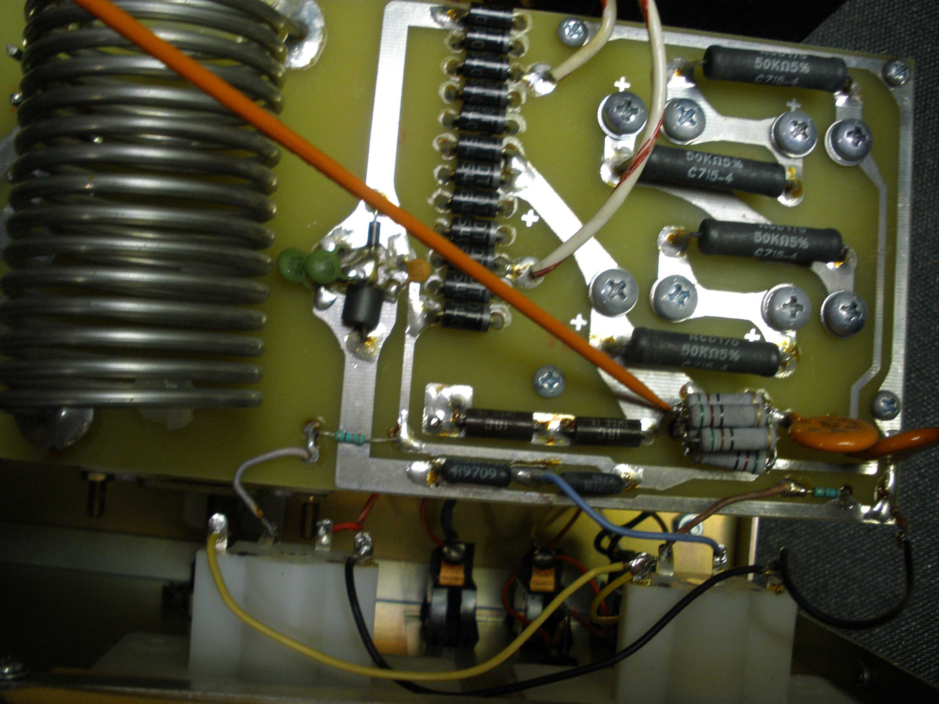
If you have not done it already, replace the original parasitic choke assembly with the new SUBASSEMBLY, PCB, PARASITIC CHOKES AND PLATE CAPS: 50-0572-1. There is discussion about how many turns of wire are proper for the parasitic coils. Be sure you are using the latest configuration with fewer turns. IMPORTANT; THE PLATE RF CHOKE IS CERAMIC. DO NOT OVERTIGHTEN THE SCREW OR IT WILL CRACK. ALSO, AVOID UNWINDING THE SMALL WIRES THAT FORM THE PLATE RF CHOKE, OR YOU WILL UPSET THE INDUCTANCE, WHICH CAN AFFECT AMPLIFIER PERFORMANCE OR CAUSE DAMAGE TO THE AMPLIFIER. If you mess this up, it will cost you about $25. The replacement choke is Ameritron #10-15197. I was able to salvage the plate choke in this amp because I had some unobtainium Q Dope, a special low loss polystyrene cement. You may be able to get by with CLEAR PLAIN nail polish. Note some colored nail polishes use metallic or conductive ingredients.
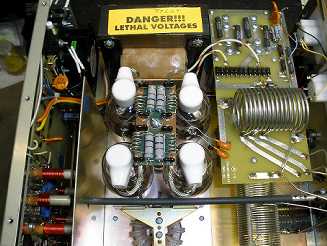
If you are going to replace the HV power supply electrolytics, do it now. Be very careful to install them in the correct polarity. If they are 10 or 15 years old, it is better to do it now, even if they test good. With the screw connection style capacitors, it is very easy to make a mistake. Do not cut corners by changing only one failed capacitor. They are all the same age. Do them ALL while you are in there. Use the parts from Ameritron to guarantee you have no mechanical problems with fit. If you are an expert, maybe 500 Volt, longer life, 105 degree capacitors could be substituted, but you will have to check for proper fit.
Once you are certain that all modifications are done correctly, reconnect the filament wires. Then you can reinstall the tube socket sub chassis back into the main chassis with the 8 screws you removed from the bottom of the amplifier. IMPORTANT: DO NOT CRUSH THE WIRES OR DAMAGE THE INSULATION ON THE FILAMENT WIRES WHEN YOU REINSTALL THE SUB CHASSIS! See how close they are to the metal standoff at the left? Also avoid damage to the red HV wire to the plate RF choke. Route it so that it can be reconnected to the Power Supply PC board, but do not reconnect it yet.
Now we are going beyond the W8JI updates. This is recommended by PA0RFI and others. I also use this mod in my Heathkit SB-200 amps. Do not use a junkbox resistor for this. Use the original Ameritron part they have in their big amps, HV ARC RESISTOR, 10 OHM 5% RCD 175P: #110-1100-1 (QTY: TWO). I took out the other support brace after I marked the location for the mounting hole to drill it. This prevents metal chips falling into the amplifier. I fabricated a small support from some bare G-10 PC board for the fuse and resistors. First, I removed the junk box resistor kludge the seller had installed. Here is how it looks when you reassemble the fuse and resistors and the HV wire from the Plate RF Choke. The new components are in series between the original HV source and the Plate RF choke. The fuse protects the amp if the tubes arc. The resistor limits the rise time of the current from the capacitor bank into the arc. This gives the fuse time to act. Use a 250 V 1 amp AC fuse, not a smaller fuse rated for 32 VDC. It is not a guaranteed protection, but in most cases it increases your chances of amplifier survival by limiting the energy stored in the capacitors, which discharges through the tube arc. In combination with the W8JI recommended mods, it all adds up.

IMPORTANT WARNING: If the high voltage fuse blows, the panel meter will still show full B+ voltage. However, the B+ will no longer be applied to the tube. (NOTE: The bleeder resistors will still discharge the filter capacitors if you turn off the AC as before.) If you apply RF drive by transmitting, the 811 grids will see that, with NO plate current. This will result in excessive grid current. If you do not detect this immediately, the tubes will be permanently damaged. Watch your meters while transmitting. If the plate current suddenly disappears and the grid current is excessive, STOP TRANSMITTING. As long as you are attentive, this modification affords some further protection beyond the W8JI mods.
I am obsessive about proper methodical test procedure order. If you prefer a "smoke test", do it the expensive way. OTHERWISE: With the new high voltage fuse OUT, test the power supply first. You should now see normal power supply voltage on the panel meter. Turn the amp OFF. Discharge the caps by waiting til the meter shows zero B+. Just to be safe, short them to ground. If you got a capacitor in backwards while rebuilding the power supply, it will show up here, without involving the new tubes. It makes it easier to troubleshoot.
Install the new high voltage fuse. Test the amp at power up, watching the B+. Bring it up slowly on a variac with a 200 watt incandescent light bulb in series, if you have one. Adjust the AC line jumpers in the back behind the removable metal plate, to the correct setting for plate voltage, if needed, at this time, using the methods described in the instruction manual. UNPLUG THE AMP IF YOU TAKE THE PLATE OFF AND SOLDER NEW POSITIONS ON THE VOLTAGE JUMPERS. THE POWER SWITCH IS NOT ENOUGH PROTECTION. YOU COULD GET KILLED, OR WORSE YET, DAMAGE YOUR SOLDERING IRON. After you are sure you wired the transformer buck/boost winding correctly, plug the amp in directly, without the variac and verify correct plate voltage at your local line voltage. Your power supply is now tested and verified to provide the correct B+ to the new tubes. Here are the W8JI instructions for the transformer taps for correct high voltage:
https://www.w8ji.com/ameritron_811h_572_amplifier_trouble_shooting.htm
DISCHARGE THE HIGH VOLTAGE AGAIN. THE PLATE CAPS FOR THE TUBES CARRY FULL PLATE VOLTAGE. Reinstall the tubes. Connect a 50 Ohm 1 KW dummy load on the output, and a 50 ohm resistor on the INPUT. This is for stability while testing. To operate the rig with the cover off, you have to disable the interlock to get the power on. Use a test clip to jumper the open contacts. If you do not know how to do this, you should NOT be working on this equipment! If not using the safety switch jumper, the simplest way to safely operate the amp temporarily is to put the cover back on, securing it with a single screw nearest the safety switch. This will exert enough pressure on the switch to close it, without having to deal with a zillion case screws. This protects the operator, and also the tubes by temporarily reinstalling the "ductwork" for the fan to cool the tubes while testing. The down side is that you can only observe the tubes through the ventilation holes, with a mirror, so you can simultaneously monitor the meters. I like to bring the amp up for the first time with new tubes using a variac with the cover off, so I can observe any tendency to arcing, like a blue or purple glow inside the envelope. That way, you maybe can shut it down before damage occurs.
WARNING: DO NOT OPERATE THE AMP WITH THE COVER OFF AT HIGH POWERS. The top cover and enclosure are part of the duct work that directs the air flow to cool the tubes and other components. KEEP ALL TUNING AT FULL POWER AT LESS THAN 5 SECONDS, WITH A 15 SECOND REST TIME. If all tests work OK, try the amp with an exciter at low powers first beginning at 5 watts, increasing in 5 watt steps while monitoring power output. If you obtain 600 watts CW, it is in spec. Then try normal SSB operation. Few power meters on the market accurately register PEAK power. If you buy one, you will spend nearly as much as you did on your Ameritron AL-811H. Here is a lab grade power meter: http://www.telepostinc.com/lp100.html If you do not want to spend that kind of money, use the 600 watt CW readings for 80, 40, and 20 and take whatever "peak power" readings your $50 hamfest used meter bargain gives you on SSB with proper suspicion. Log these exciter power settings and amplifier knob settings for each band, so that you can quickly tune up the next time. If all is OK, you have an AL-811H as good as any shipping from current production. Success! You can put the rest of the cabinet screws in.
When I finished with this amp, I got a good solid 600 watts CW on 80, 40, and 20 meters. SSB output as measured on a good peak power reading meter is higher due to the higher plate voltage in intermittent modes. If your meter is not good at peak power, do not push the amp harder to make it look good on your meter. If it meets spec on CW, use those settings for SSB and don't look at your power meter if that bothers you. 160 meters and the bands above 20 meters are known to produce less power. The 811 was originally designed as an AUDIO tube, and hams used it for RF. Driving this amp harder than 600 watts CW on 80, 40, and 20 meters or about 400 W CW output on 10 meters is unreasonable, and reduces tube life without gaining any signal level noticeable at the receiving end. The 10 meter output will never achieve the 40 meter level, regardless of mods. The tank circuit is working hard to give performance on 160 to 10 meters, and the plate capacitor has limitations on minimum capacitance, and inductance in switch wiring is limiting efficiency. That is why vernier knobs are essential, and all the readings for the plate tuning are squashed together at the higher numbers above 40 meters. Even if you could correct those problems, the 811A was designed as an audio tube, and internal lead lengths are excessive for full performance above 20 MHz. The 572B is built with the same long grid leads; they could have provided a second grid lead to the unused socket pin, which would have helped some. Plus, 811s and 572Bs ain't what they used to be. That is why the big amps for serious contesters use ceramic external anode tubes with short leads. It is much easier to get VHF performance from those external anode ceramic tubes with their short internal leads, instead of taller glass tubes. Most glass tubes have a frequency derating which requires lowering the plete power at a certain point. 6146s, for instance, must operate at reduced power on 6 or 2 meters, for the same reasons; at least they are designed as RF tubes. The Harvey Wells Band master pushed an 807 to operate on 2 meters, but that was all they had at the time; it is nuts to attempt that now, even if you use reduced power. A curmudgeonly old amp designer would probably observe that if you have an RF amp with more than 2 tubes, you are using the wrong tube. The AL-811H and the AL-572B are good economy amps, but do not gripe if you do not get Alpha amp performance for that price. The world is changing, and the new monster FETs can achieve 1KW with a single device. Within a decade, most amps will be using FETs.
NOTE: THE ORIGINAL RCA TRANSMITTING TUBE MANUAL STATES THAT 811A TUBES SHOULD SHOW NO COLOR (NOT EVEN DULL RED). If you shift gears on your car when the tachometer is 1000 RPM above REDLINE, my approach may not appeal to you.
After I completed the W8JI mods, I still had the problem of the clicking or popping noise in the receiver. It happens at a rate of about once every 2 seconds. The first time I heard it, I assumed it was an electric fence. The 200 ohm resistors are not present in current production, at least according to manuals posted on the Ameritron site. Neither is the W8JI cutoff bias modification. Maybe it does not work in all cases, or it is not required with tubes selected by RF parts or Ameritron. If you have this problem now, and need new tubes, I would recommend using the Cetron tubes from RF parts (they are 100% tested and burned in) or from Ameritron. Surplus Sales of Nebraska still has Cetron 572Bs in limited quantities, but I do not know their warranty policy, or if the tubes are 100% tested and burned in like the other 2 sources. The AL-811H still is a pretty good little amplifier (but with an annoying habit). I did clean the old open frame relay with a couple swipes of a small strip of paper. Then I tested the output power on various bands, and let the plates get hot with a lengthy SSB transmission at full specified power. The ticking disappeared - at least for now. But the owner reports it has returned.
The three tube AL-811 seems to be fading away; no neutralization and a number of other lacking features may make it worth while to spend more on the 4 tube model, which has the essentials. The AL-811H and AL-572B are still in current production, so the clicking or popping problem is apparently controlled, with tubes from qualified sources. I DO NOT RECOMMEND REMOVING THE ARC DEVICES FROM A CURRENT PRODUCTION AMP TO STOP THE CLICKING NOISE. Sending your damaged transceiver back for repair because the front end is nuked by a tube arc is a lot more annoying than dealing with the clicking noise by setting the AGC to fast. OBJECT LESSON: DON'T BUY TUBES ON THE CHEAP.
This concurs with the N6MW data on this page:
REALLY GOOD COLLECTION OF DATA AND TESTS, AND 572B MOD:
http://n3ujj.com/manuals/Ameritron%20AL811H.pdf
Tube Dissipation is always the biggest field problem. If you remove the four 811's and replace then with three 572B's, there will be virtually no change in SWR or neutralization. The available dissipation will be more than 2-1/2 times higher, and the thermal lag of a 572B is significantly longer. This results in a significant life increase if you are a bit slow on tuning or run high duty cycle modes at high power. IMO if you have life problems with tubes that you can't cure with a change in operating methods then the simple solution is to use 3 572's to replace the four 811's, leaving the socket nearest the fan (right rear socket) empty and removing that plate cap.
73 Tom
NOTE: SEE THE FAN MOD WITH TOP COVER MOD BELOW FOR 572B MOD
AL-811H FAN AND COOLING SYSTEM DATA (essential if upgrading to 572Bs):
https://www.w8ji.com/al811h%20fan%20speed.htm
COMMENTS ON RATINGS OF NEWER 811 TUBES:
https://www.eham.net/ehamforum/smf/index.php?topic=1038.0;wap2
"If you want your tubes to last don't look for more than 500 watts cw output or perhaps 550 watts pep on ssb out of a four (4) tube 811A amplifier. Don't look for more than about 375 watts cw or 425 watts pep out of a three (3) tube model. And on RTTY, which is a 100% duty cycle mode, don't look for more than 350 watts or 275 watts respectively. The ratings I've suggested are approximately 1 db down from claims for cw output and only about 1.5 db down for ssb output. To put a db in perspective, it is the smallest change in power that is barely discernable, and then not by everyone."
"In any event those horizontal fins distinguished the 65 watt ICAS tubes from the 60 watters. In all likelihood, the Chinese tubes are no more than 55-60 watts in rating, no matter what"
NOTE: One S unit is considered to be SIX dB. Beating up the expensive tubes for one dB is not logical. If you dispute this, join the local chapter of "Meter Benders Anonymous", to learn to accept those things you cannot change.
INDEX OF W8JI ARTICLES ON THE AL-811H AND ASSOCIATED TOPICS
REQUIRED READING. SUPPLEMENTAL TUNING INSTRUCTIONS:
https://www.w8ji.com/al811h_and_811_tuning_supplement.htm
AL-811H DRIVE AND POWER DATA:
https://www.w8ji.com/al811h_schematic.htm
NEUTRALIZING INSTRUCTIONS:
https://www.w8ji.com/neutralizing_al811h.htm
NOTE: Neutralization is adjusted by mounting the metal bracket near the left hand tubes in different holes. The adjustment procedure is explained in detail. It should not be necessary, if you are using the tubes the amplifier was intended to employ.
WHY SOME 811s ARE LOUSY (and that popping noise in standby mode):
https://www.w8ji.com/811a_tube.htm
"Some recent 811A tubes have an unusual remote cutoff, and will not fully cut off with normal cathode self-bias. This is caused by the grid being off-center vertically, or not having enough winding length. In this case the simplest modification is to add a 11.5:1 very high resistance divider, 750K 2 watt metal type and 100K in series. This divider can be used to force the cathode high." I did not try this (less expensive and easier) mod. The 200 ohm 20 watt did not work in our case, and neither mod is shown in manuals for current production AL-811H amplifiers. This cutoff bias mod appears to me to be logical at least, since it directly addresses the problem. But the gas arc tube protectors are firing at 150 VDC. I presume they are firing at PLUS 150 VDC due to inadequate vacuum in inferior tubes. So the W8JI DC bias mod may not work either, since it is at a lower DC voltage. If you have this problem, you might give it a try. If it works, please let me know, and I will correct it on this page. The Heathkit SB-200 uses minus 130 VDC cutoff bias on the GRID, and mine is stable in standby with the Svetlana 572Bs, contrary to W8JI comments about the Svetlanas. The Svetlanas were better quality tubes than the current crop of Chinese tubes. But that amp is an entirely different design. W8JI is correct about the Svetlanas in the AL-811H. The AL-811H applies positive bias in the CATHODE circuit. Maybe the Yaesu linear does not like Svetlanas, I did not analyze its circuit. My Heathkit Warrior used bias circuitry similar to the SB-200 and worked OK with whatever 811s I installed. The Warrior also used neutralization.
At this point, I do not know how to fix the clicking problem other than using selected tubes. I am speculating that it may be a combination of improper tube grid construction and inadequate vacuum in modern Chinese tubes. In any case, it is not W8JI's fault. The original amp worked fine with American made tubes. He has made a good effort to extend the design life of the AL-811H amplifier in the face of parts procurement problems.
MORE ON THE RESISTOR AND CHINESE TUBE CUTOFF AND POPPING NOISE PROBLEM:
https://www.w8ji.com/al811_update.htm
TROUBLESHOOTING TIPS AND HOW TO SET THE LINE VOLTAGE JUMPERS:
https://www.w8ji.com/ameritron_811h_572_amplifier_trouble_shooting.htm
AL-811H RELAY STICKS, HOW TO FIX IT:
https://www.w8ji.com/relay_cleaning_and_life.htm
OTHER'S ARTICLES ABOUT THE AL-811H
PA0RFI MODS AND DISCUSSION:
https://pa0fri.home.xs4all.nl/Lineairs/AL-811H/AL811H%20modifications.htm
OTHERS COMMENTS ON PA0RFI MODS:
https://www.eham.net/ehamforum/smf/index.php?topic=113758.0
PA0FRI has done some extensive writing; check his web site. You can decide for yourself what to think. I have to agree his approach to the single point grid ground is probably not the way to go. He has some mods to increase 10 meter output. It may require redesign of the parasitic chokes. I did not try any of this, so I have no comment. W8JI had numerous exchanges over the parasitic choke design, and did extensive analysis with equipment I cannot afford. I recommend you stick with the design engineer's guidance, rather than a third party, unless you own a lot of expensive equipment. Rather than buying engineering lab grade test equipment and learning how to use it, you might be smarter to either buy a premium grade amp with the money, or accept that you own a good economy amp and enjoy operating it within its design specs.
BACKGROUND AND GENERAL SUMMARY
I worked on this older model AL-811H for a new ham, who bought it used, thinking he had a bargain. The cosmetics were 9 out of 10, but the electrical condition poor. Also, it was a pre-2011 model, which lacked some of the updates to accommodate the shortcomings of current Chinese made 811 tubes. He went through our club's licensing classes and Don and I personally were the VE's present when he took his tests. I admired his hard work to obtain his operating privileges. So I took this project on to get him out of a jam. I do not do repairs any more, I am retired. Please do not ask. There are others out there like the Amp Lady or even Ameritron who will do great work on amplifiers and other gear. Support them with your business.
Tom, W8JI, is the creator of a long list of amateur gear; the AL-811H delivers all the quality features at just the right price point. W8JI also has a number of individual pages discussing the various design and modification and repair techniques for this line of amplifiers. A newcomer would find that overwhelming. In the process of upgrading and repairing this AL-811H, I spend a lot of time reading these informative pages to distill the information I needed to complete the work. I am posting this information as a supplement or digest of the essential information. I am not ripping the information off; I have given credit where it is due, and linked back to the original authors. But I am adding some of the photos I took while repairing this, and adding some comments on problems I encountered with this particular project. The photos may give different views showing you how to get the job done. Do not rely on this page alone to do the work; go back to the referenced pages and read up on it first. At the end of this article, there is a bibliography of the pages of others who have written about the Ameritron AL-811H or its cousins as well. Other authors were helpful in preparing me for this job. I reference their source information as well. Some authors had questionable suggestions. I leave it up to you to decide what to do with your amp, and show you what I eventually did to this one.
I encourage you to buy a new amplifier, especially if you are a recent recruit. Doing this kind of work with high voltage present is not for the inexperienced. This amplifier was sold used to my newly licensed friend. The seller KNEW its condition, and that is why he dumped it. This shameful conduct is unfortunately all too common. Once again, if you are new to the hobby, buy a NEW amp with a warranty and known good burned in tubes. My friend made a reasonable attempt, but knew when to quit. I did a cost accounting for the parts and labor, which made this used amp more expensive than an up to date, new amp, with a warranty. First, the tubes were bad. One did not even light. Another did not move the tube tester needle. Yes, I have a tube tester that will do transmitting tubes; get the right tools for the job, if you are going to repair stuff, at least a tube checker for receiving and smaller power tubes. You can build a test jig from junk parts for big RF tubes. The remaining two tubes were barely alive, not even useful for basic functional tests. The parasitic choke resistors were totally fried. My friend bought the new PC board assembly for the parasitic chokes and some new tubes. The PC board went in OK, but the Plate Choke winding was damaged in the process. I fixed it using Q Dope, a low RF loss polystyrene cement, which is no longer available. The Plate Choke cost is not figured in the job, but it would have been substantial as well. Underneath the sockets, the original R - C network from grid to ground had been rebuilt using inductive resistors, possibly aggravating the parasitic choke failure.
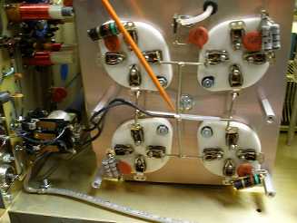
Also, my friend bought new tubes at a small savings from a supplier other than Ameritron or RF parts. These suppliers are the ONLY sources I recommend. RF parts 100% tests and burns in all tubes, and provide a great warranty. Some of the on line sellers are offering tubes that RF parts REJECTED. Buyer beware. Luckily, these did not arc over and do even more damage. Notice in the photos the huge size of the glass envelope. The reason for this is that the glass is not rated for high temperature like the slender Svetlanas of the past. The extra clearance from the hot plate avoids the glass melting. The bigger glass tubes are a little harder to install, working them past the Parasitic Choke PC board. Also, air circulation is important, and that may not be as effective with glass envelopes this size. While we are on the subject of arcs in Chinese glass tubes such as the 811 and 572B, there was discussion of not manufacturing any more of these economy amplifiers using them. Fortunately, a new Chinese supplier stepped forward and worked with RF parts and Ameritron to get the manufacturing process straightened out. You will never again find tubes of the quality standard of RCA or GE, but the new Chinese tubes from reputable sources are a good value. For long life, we should operate them at the specs of the original 811, not the 811A, due to the shortcuts of the new plate construction. We should be grateful that a reputable Chinese manufacturer responded to the problem by correcting his manufacturing process. I hope the others follow suit and help keep our hollow state rigs on the air. In the meantime, avoid the cheapest priced products. In addition to the aggravation, they may cost you more in the long run.
Don and I were aware of the growing glass tube quality problems, and that is why we decided to go with the Ameritron ALS-1300. Now, I would have gone with the ALS-1306 for better 10 meter output. With a solid state amplifier, you do not put your transceiver at risk if a tube arcs; there are no tubes and therefore no need for all these modifications. Over the life of the amplifier, tube replacement will also be an ongoing expense. If quality glass tubes eventually cannot be obtained, the amplifier would be useless.
|