|
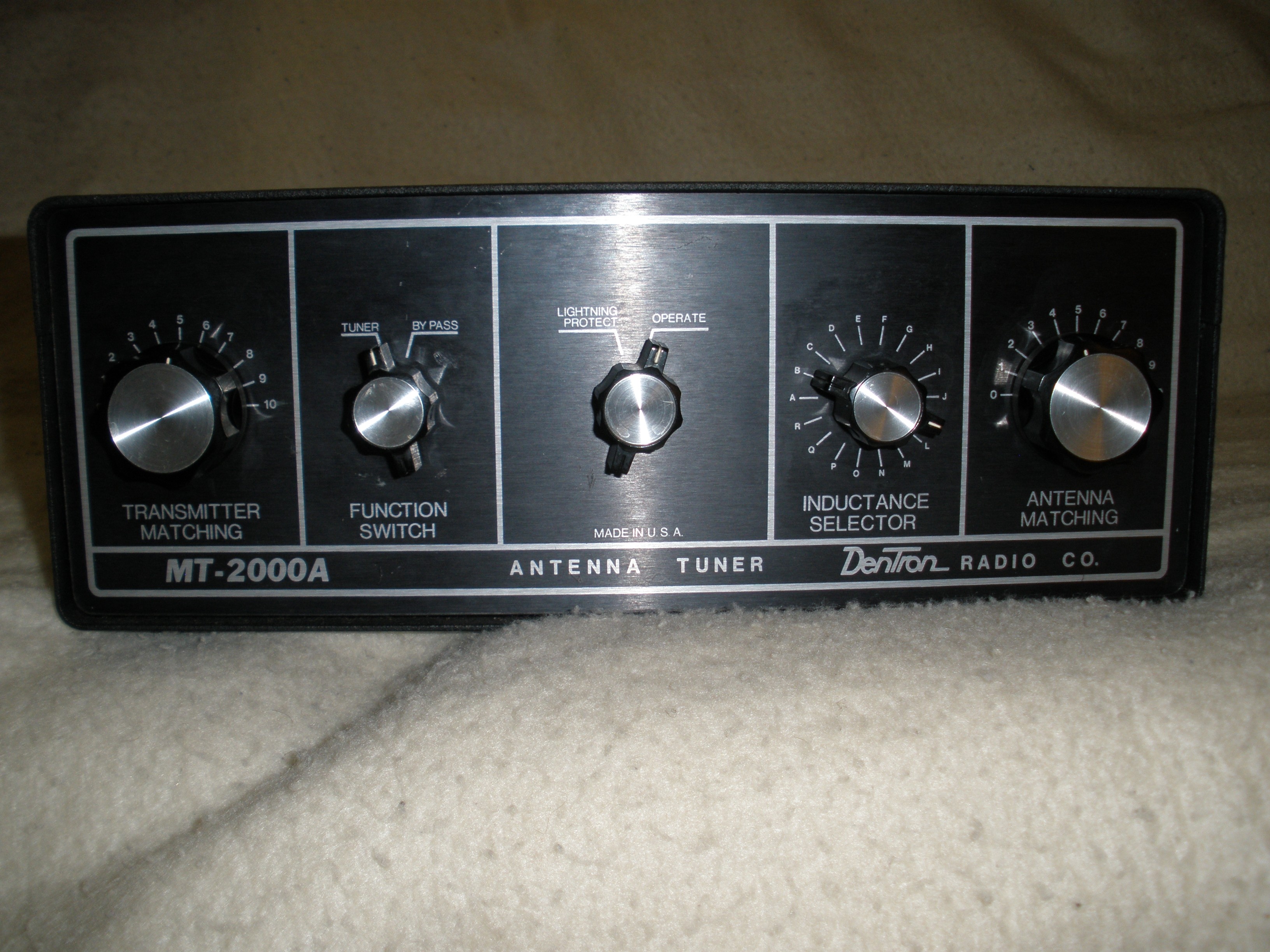
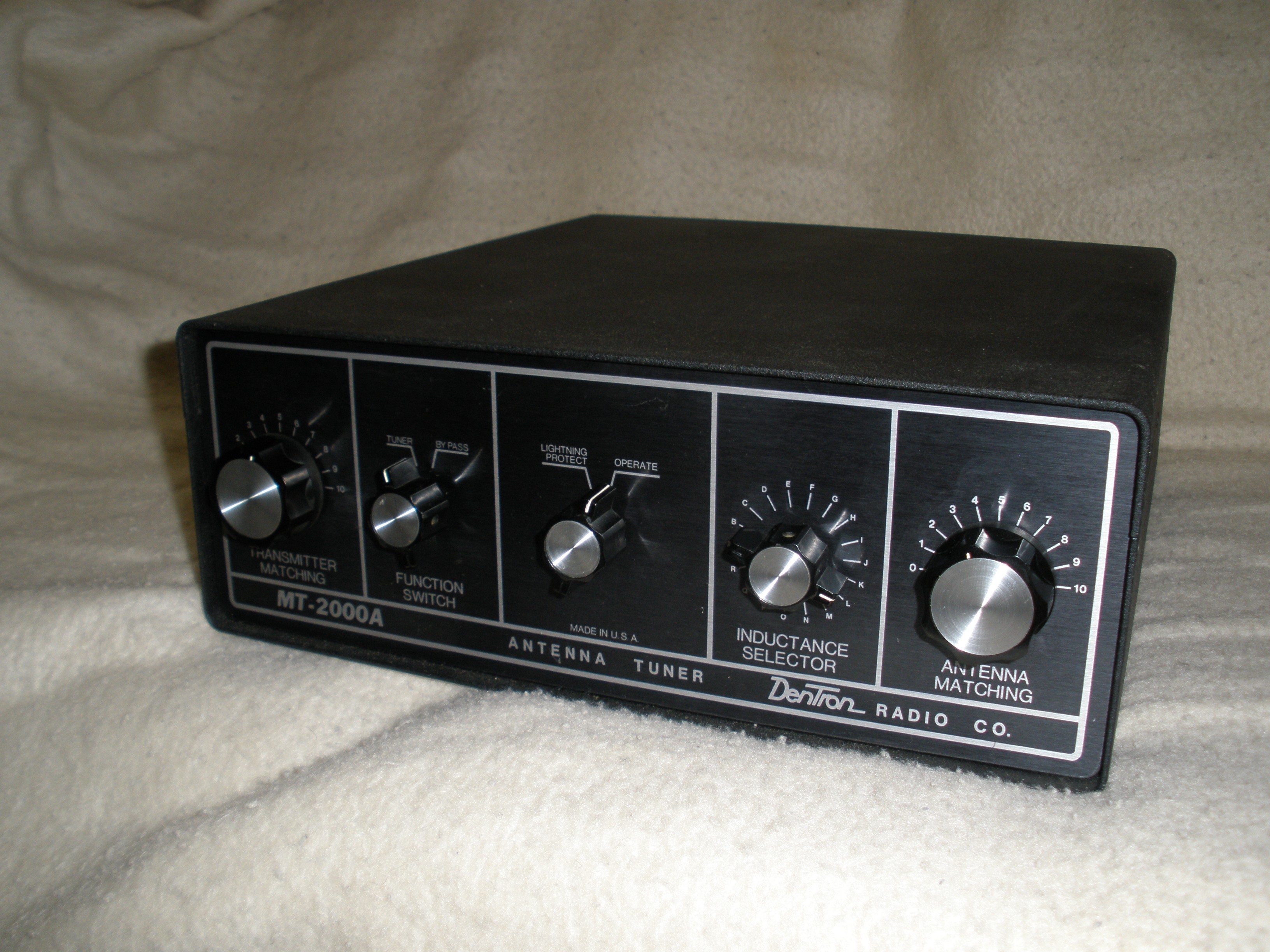
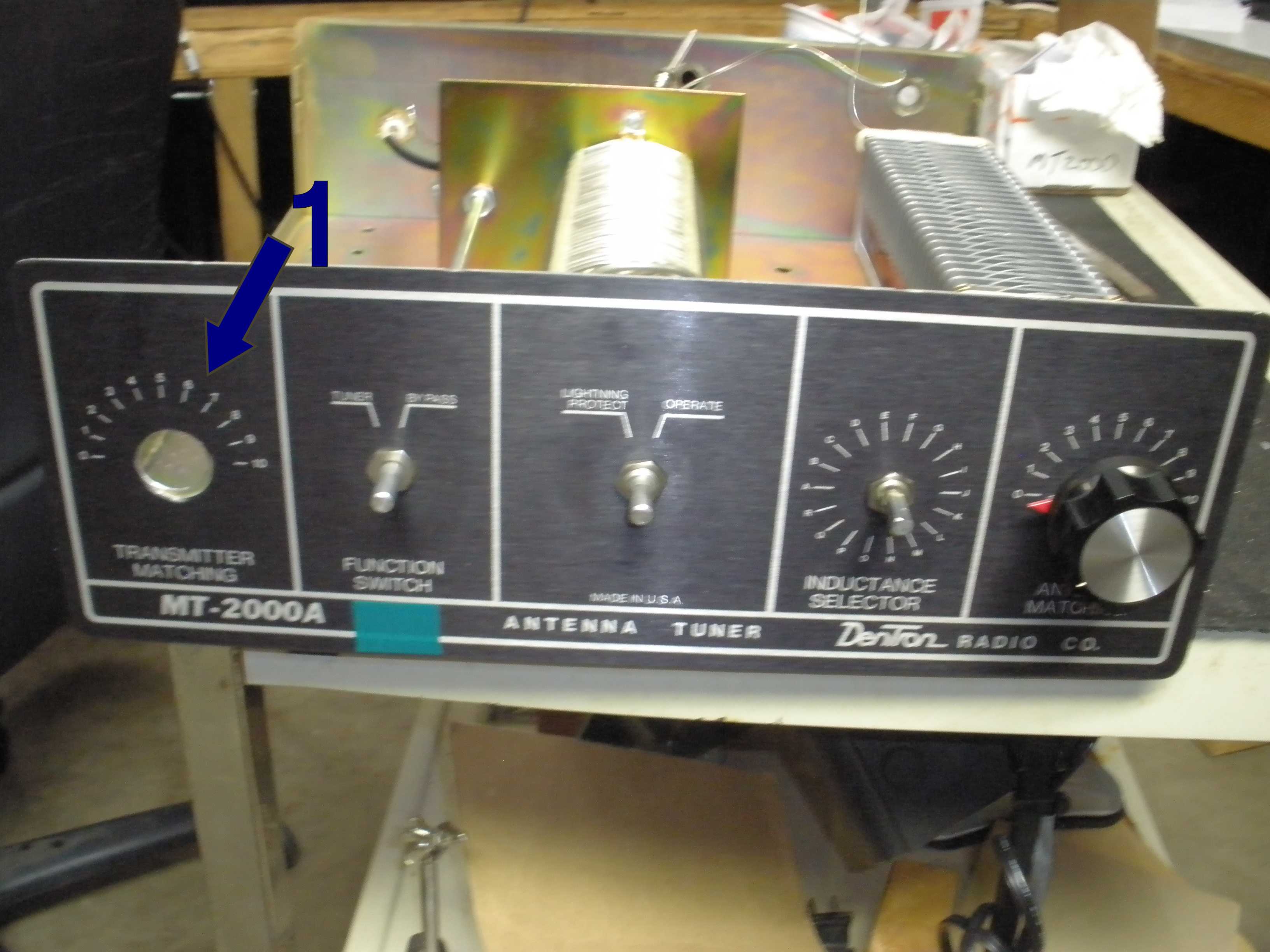
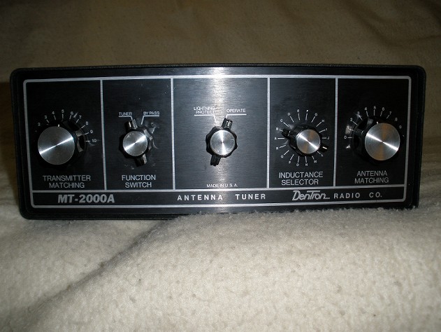
Of all the transmatches I own, this is my favorite. It consistently gets a 5 rating on eham reviews. It does not attempt to add "features" like a power or SWR meter or antenna selector, which I prefer to add separately. I am very picky about those items, and prefer to choose them separately. I have never found it lacking in performance. It matches any antenna I have ever connected to it. It handles all the power from my Heathkit SB200, about 700 Watts output with no signs of arcing or heating. I recently upgraded to a legal limit ALS-1300, and it works fine with that, for coax fed antennas. All the internal components are super heavy duty compared to commonly available new units. This transmatch comes in a variety of flavors. The early Dentron Super Tuner is rated at 1 KW; I have run it at 100 Watts AM (equivalent to 400 Watts or more PEP) with no problems. A smaller 160-10AT looks like it will be OK for a 100 Watt CW or SSB signal; I have another page for that tuner, with a mod which works better on 160 and 80 meters. A big brother is the 3000 Watt model, which is the exact same components as the MT-2000A, except it includes a SWR/Power meter. In the photos below, you can see the MT-2000A chassis is punched for the extra accessories included in the MT-3000. These all typically go for $90 to $300 depending on the power rating at swapmeets or better web sites. The authoritative clunk of the switch speaks of the quality and dependability of this well built unit. I quickly became dissatisfied with the match range and reliability of the Ten Tec 238 transmatch reviewed elsewhere on this page. These Dentrons are definite keepers. 5 out of 5.
Have you ever seen a manufacturer dare to state the insertion loss in dB? Read the specs included later to see. QST often finds even 2 or 3 dB on recent transmatch product reviews.
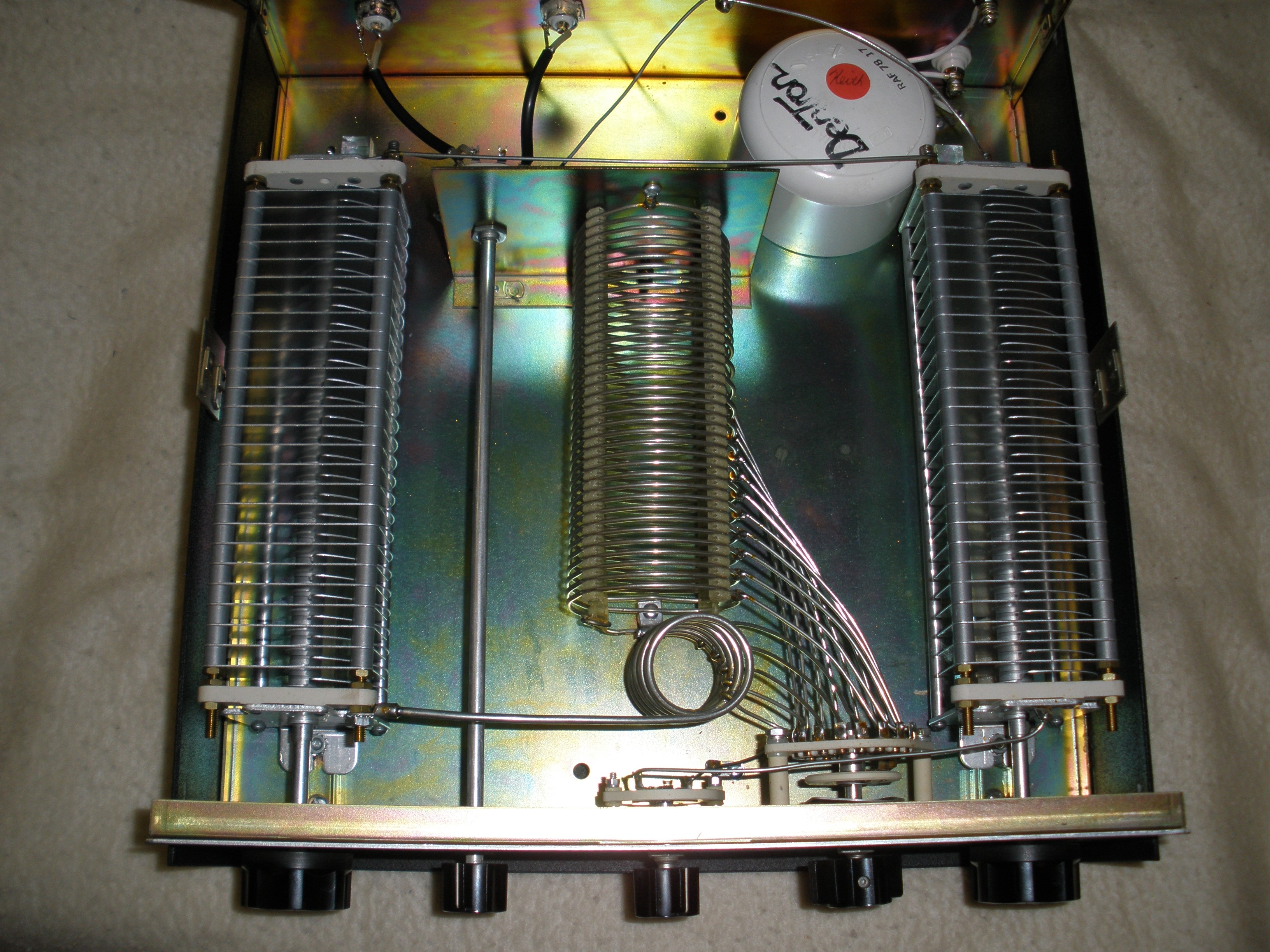
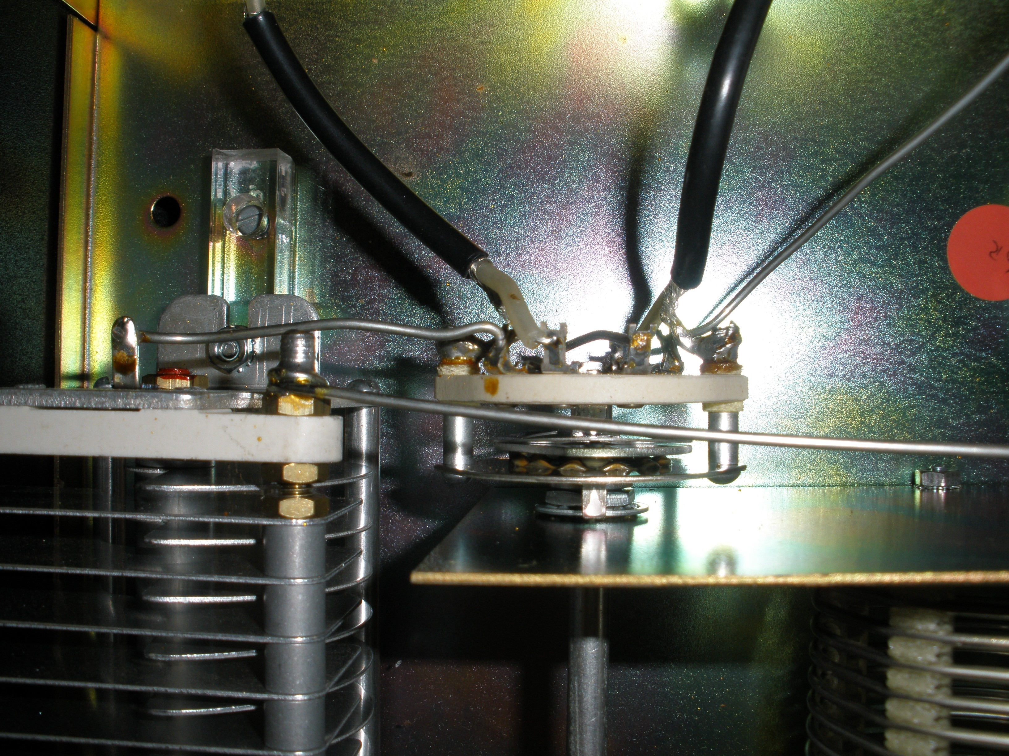
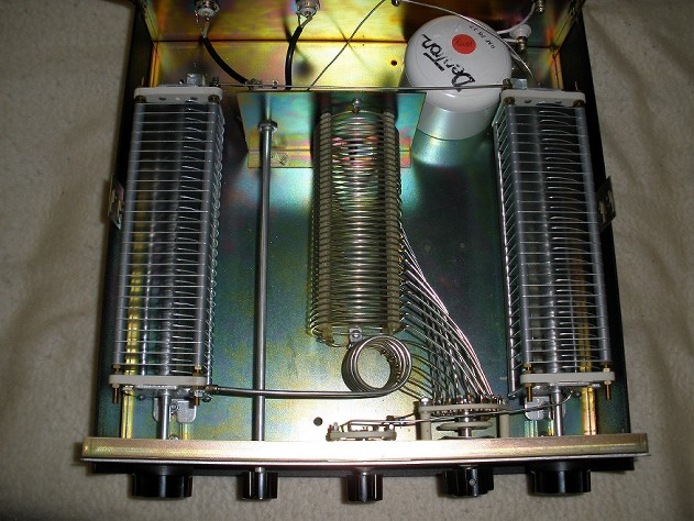
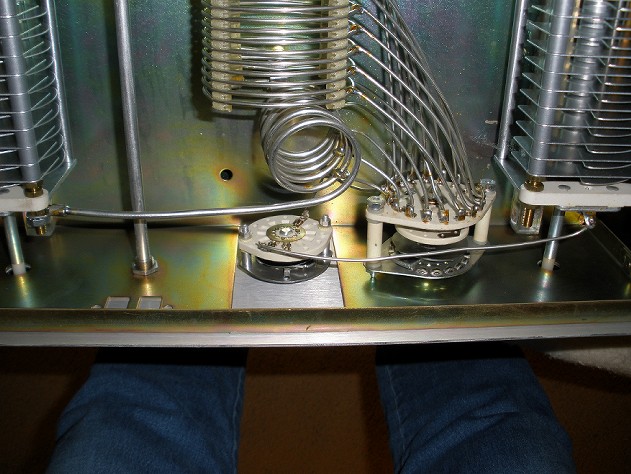
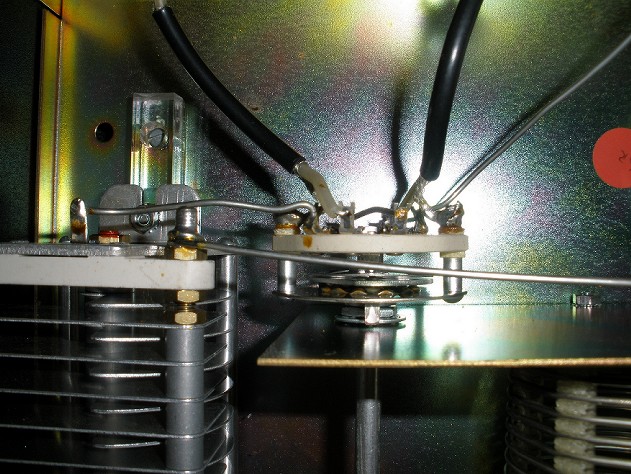
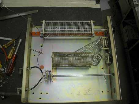
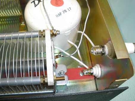
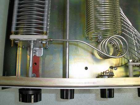
See the interior photos to understand the detaiiled notes below.
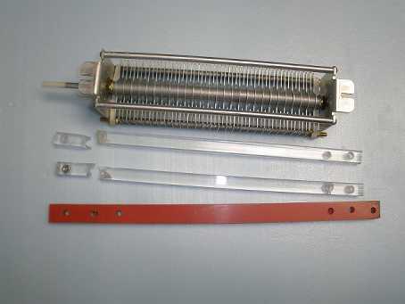
The only problem I encountered was the breakage of the lucite plastic insulators beneath the tuning capacitors. Some glue corrected this easily. Everything else is built like a tank. This unit weighs 18 pounds due to the substantial cabinet.
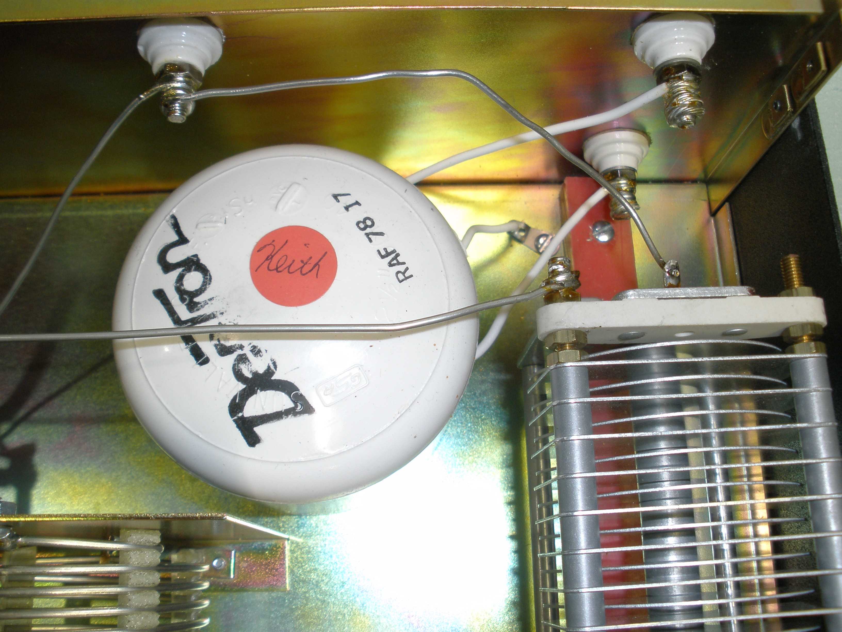
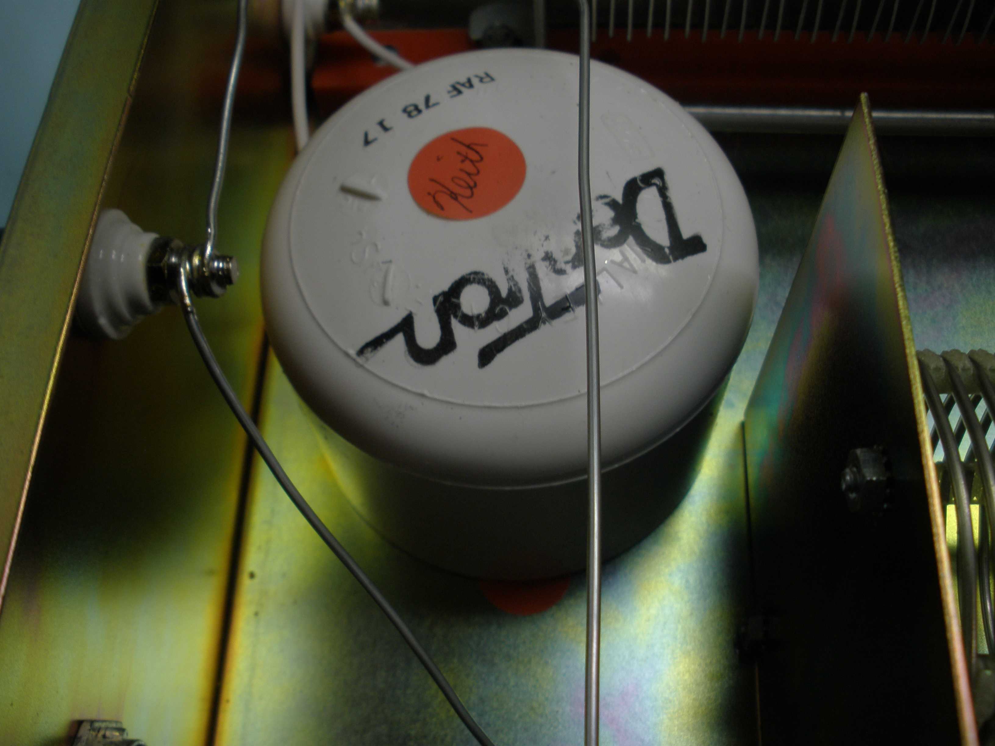
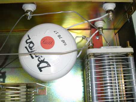
The lightning protect switch was stuck in place when I bought it used after a long period in storage. I applied some WD40 and let it soak in several times. I removed the knob and used vise grips to carefully rock the switch shaft till it became operable. Since I have external grounding type antenna switches, this feature is not used at my station. I always disconnect the antennas outside at a grounding rod when not in use during lightning season. If you find one at a swap meet with this switch frozen in the lightning protect position, just disconnect the wire to the right hand capacitor.
The capacitor tuning shafts have plastic extensions. If these ever break, I plan to use a ceramic shaft coupler and add surplus vernier reductions to the stock knobs. At higher frequencies, the tuning is a bit touchy, but not to the point that you cannot use it in stock form.
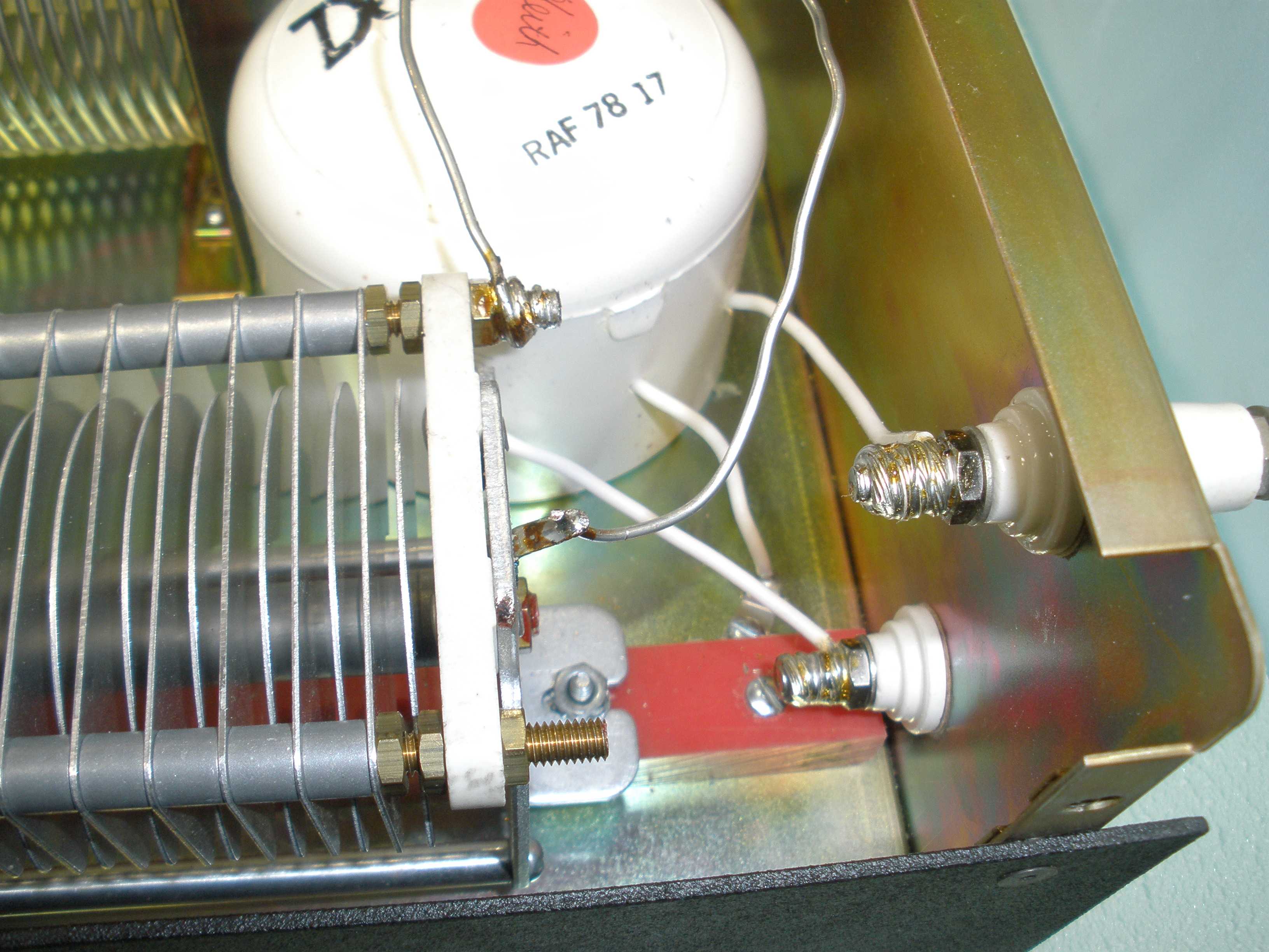
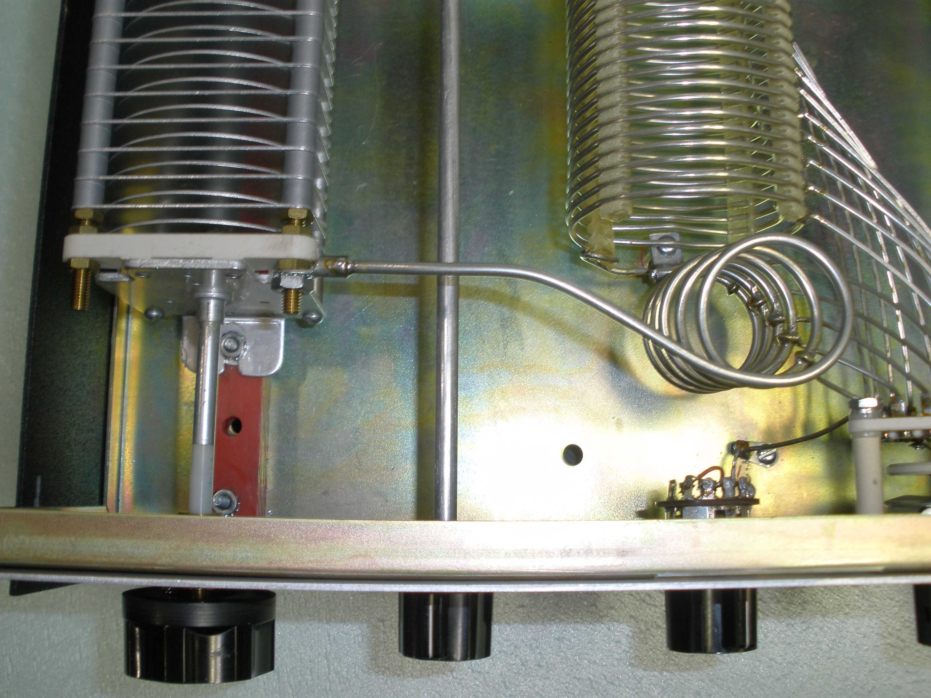
Building a transmatch that covers 160 through 10 Meters is a challenge. The capacitors have to have a maximum capacitance sufficient to function at 160 Meters. This makes it difficult to achieve minimum capacitance values to work at 10 Meters. You may find that the small vertical coil in the front of the cabinet can be adjusted by spreading its top two turns. This may allow better match on 10, 12, 15, AND 17 Meters. Be very careful you do not stress the switch while making this adjustment. Support the connecting wire to the switch with pliers to remove the stress from the ceramic switch.
The long piece of buss wire attaching the rear of the capacitors might benefit from replacement with wide copper strap or heavier guage wire. I plan to experiment with this later when appropriate.
The coax wires inside the transmatch could be replaced by RG8 mini.
EXTRACT OF SALIENT SPECIFICATIONS AND INSTRUCTIONS FROM MANUAL:
Note - Full manual available at http://www.radiomanual.info/schemi/ACC_matching/Dentron_MT-2000A_user_WA0KKE.pdf
SPECIFICATIONS:
- 1.8 to 30 MHz Continuous
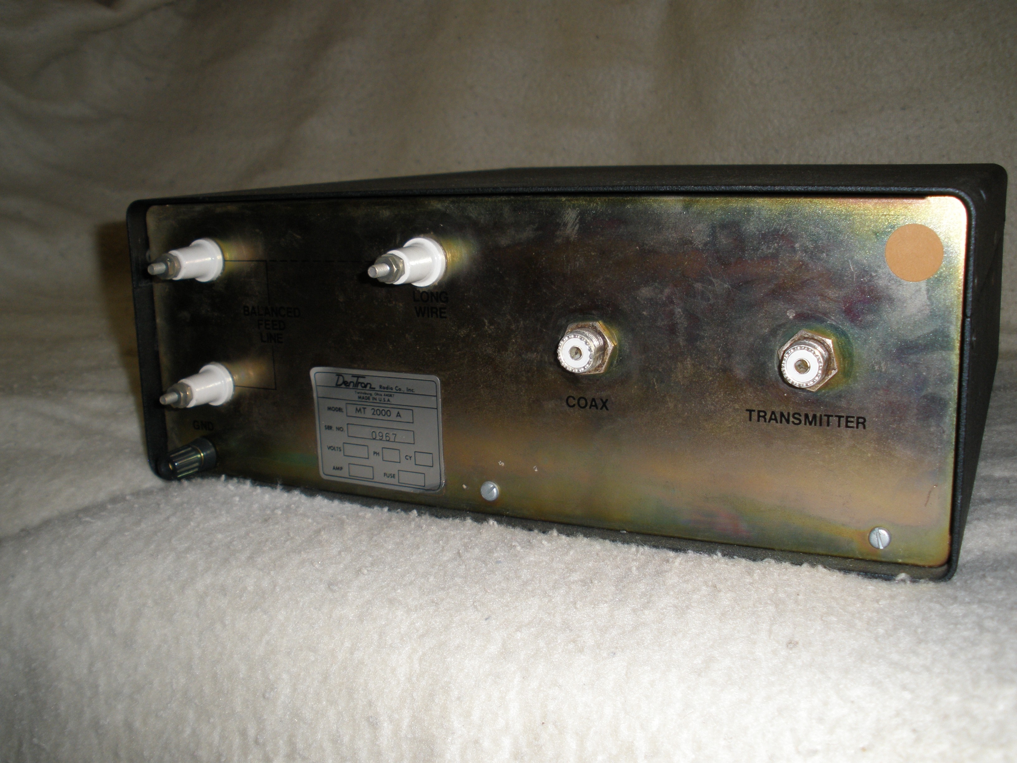
- Input Z : 50 Ohms resistive
- Output Z: Coax 50 Ohms nominal but may be a few Ohms to HI-Z
- Long Wire: High or Low Impedance
- Balanced Line (4:1 Balun inside tuner cabinet): 75 to 600 Ohms
- POWER RATING: 3000 Watts PEP
- INSERTION LOSS: 0.5 dB or less after tuning
- Dimensions: 5.5" H X 14" W X 14" D
- Weight: 18 lbs
- TRUE BYPASS SWITCH is an actual pass- through
- Antenna grounding switch included
- No AC or DC power required for operation
NOT INCLUDED:
- SWR or POWER indicator
- Antenna Selector
SUPPLEMENTARY TUNING INSTRUCTIONS:
- SWITCH POSITION A for lowest frequency (160 Meters)
- SWITCH POSITION R for highest frequency (10 Meters)
- NEVER ADJUST ANYTHING WITH FULL POWER APPLIED except for tuning capacitors!
- NEVER APPLY POWER WITH LIGHTNING PROTECT SWITCH SET TO PROTECT. ALWAYS SET IT TO OPERATE BEFORE TRANSMITTING AT ANY POWER LEVEL!
- TUNER-BYPASS SWITCH ONLY AFFECTS COAX CONNECTOR. It does not function on open wire or balanced connections.
- NEVER CONNECT MORE THAN ONE ANTENNA TO THE MT-2000A.
- FOR UP TO 10 MHZ: Set both capacitors for mid range (5). Adjust Inductor for maximum receive signal or background noise. Apply less than 100 Watts and adjust for minimum SWR.
- FOR 14 MHZ AND ABOVE: Set both capacitors to 8. Adjust Inductor for maximum receive signal or background noise. Apply less than 100 Watts and adjust for minimum SWR.
|


HOW TO ADD VERNIER TUNING TO THE DENTRON MT-2000A TUNER
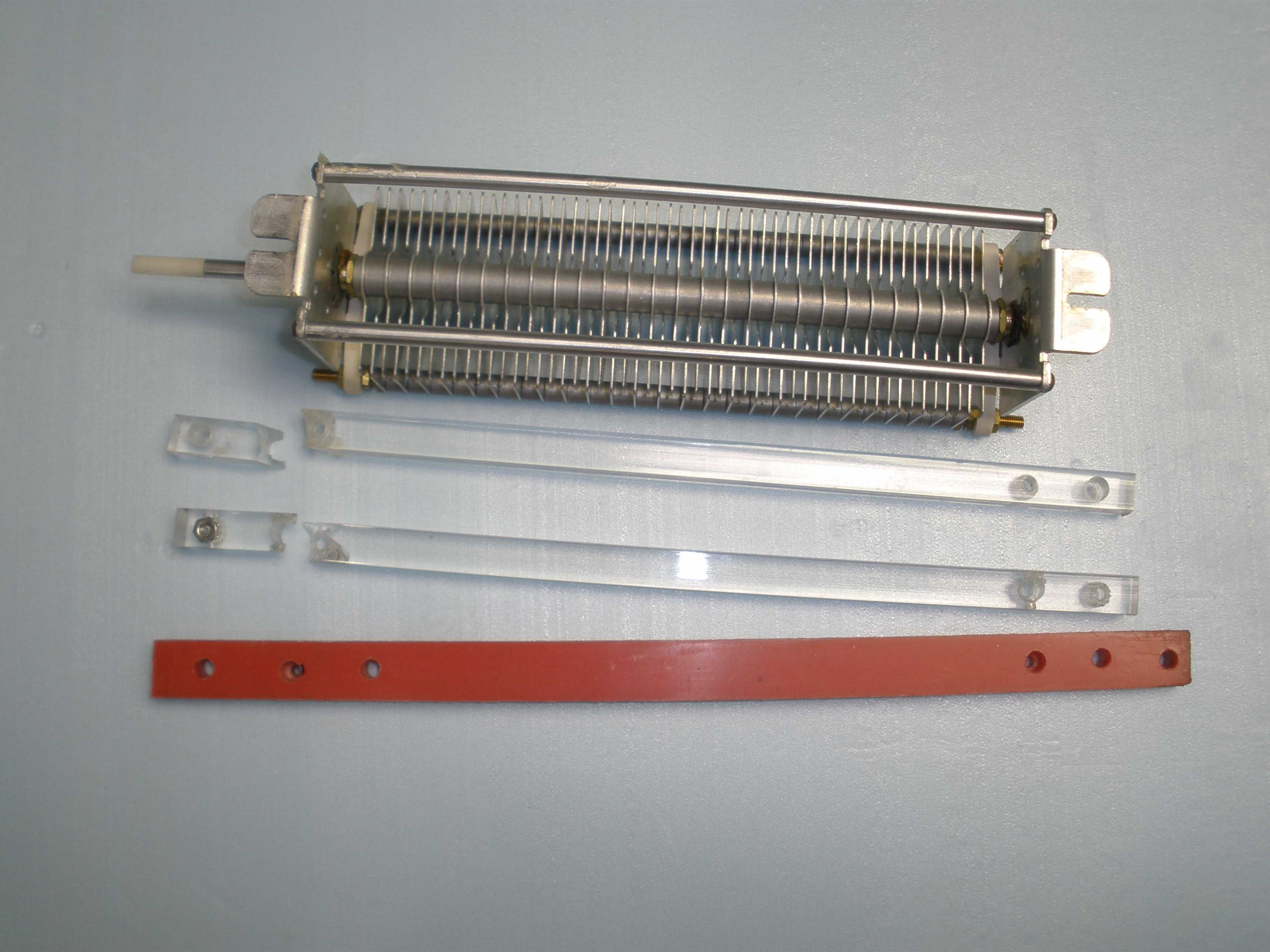
The capacitor tuning can be jumpy and critical as you approach SWR minimum, as I noted above. If you really want to adjust SWR for exactly 1:1, a gear reduction to the capacitor tuning is a big help. The parts employed for this improvement are available from Ameritron, because they use the same technique to get smooth tuning of their amplifier plate tuning controls. The Jackson ball bearing drive and the red pointer (the smaller one) are what you need to buy. Also, this photo essay shows replacement of the plastic insulator rails which mount beneath the tuning capacitors. These fail when the unit is shipped or handled roughly. The plastic appears to be a brittle lucite, which is a good insulator, but not robust mechanically. I used some scraps of nylon from a project I did at work years ago. I learned from my grandfather (who went through the depression) to never throw out good pieces of a 2 X 4, because you never knew when you would need a piece of wood to fix something.
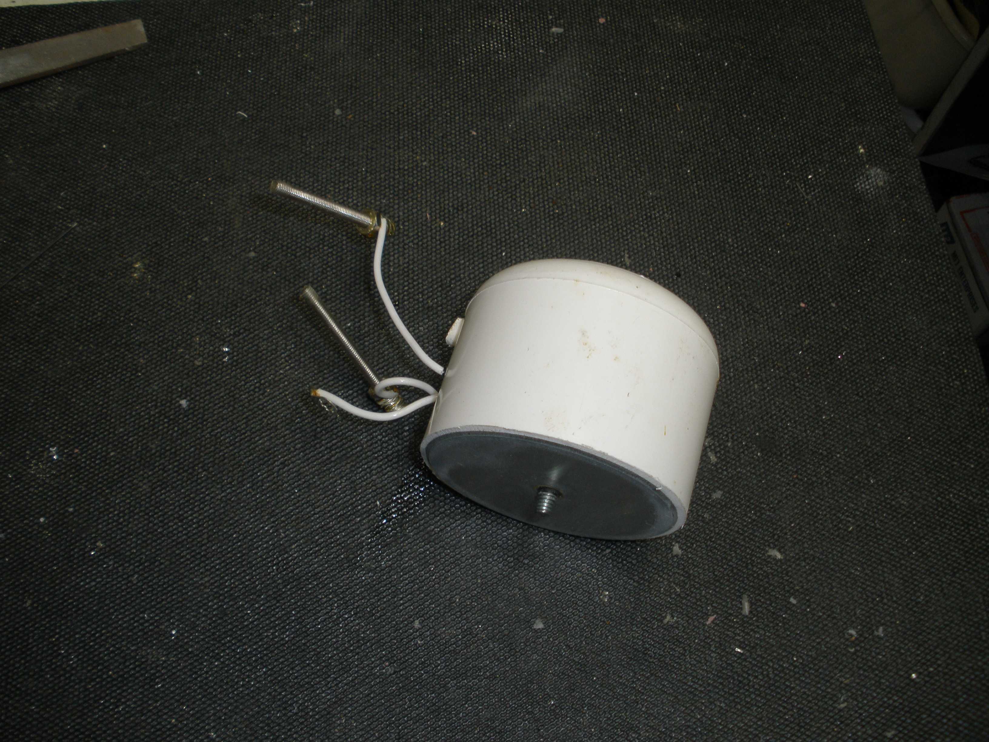
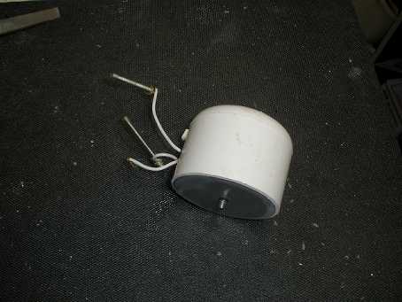
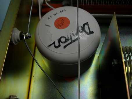
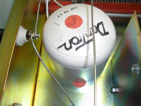
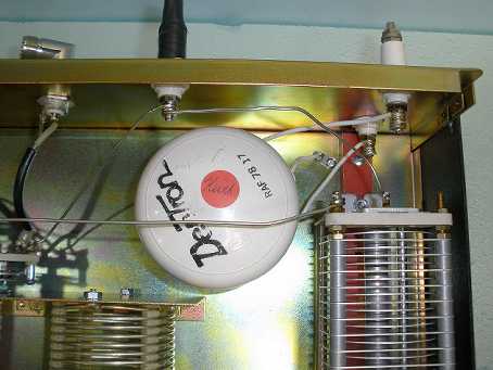
You may find that the leads on the balun are too short to reinstall it about an inch and a half to the left of the original position. You may either leave the balun out or extend the wires. This is a voltage balun; you should probably be using a modern current balun, if you need one. In that case, it needs to be mounted externally anyway. As baluns of this vintage go, this is a large robust one, and you may find it meets your needs just fine. It is potted in insulating material, so its arc resistance is better than you will find elsewhere. Teflon wire is used, for better heat resistance than standard insulation. Dentron gives extra attention this type of detail all through their product. I plan to do some tests on the balun that did not reinstall easily, and post data here later.
I chose to remove the "lightning protect" switch permanently and replace it with a junk rotary switch, to preserve the appearance of the tuner. This feature can cause problems if you inadvertently leave it in the wrong position. The manual warns you about this, and rather than risk that outcome, I chose to disable the switch altogether. It also does not afford much true protection in the case of a lightning strike. I disconnect the coax antenna wires outside the house when the station is not in use. In any event, it does not need to be taken out to do these mods.
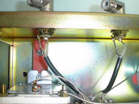
The coax used in the Dentron MT-2000 is RG-58/U. You could replace that with RG-8/U for better power handling capacity. This might be important if you use an end fed wire, since that coax section on the output is at higher voltages than might be expected for a coax fed antenna. Alternatively, heavy solid buss wire or copper strap could be used; in that case, some small SWR will result on 15 and 10 meters when you operate the tuner in bypass mode. I chose to leave it alone, since I had no problems at this time. Have whatever parts you need for this work on hand before beginning.
You will also need to order the following parts from MFJ-Ameritron before you begin this project. Ameritron is kind to amateur radio homebrewers by selling parts used in their products, but PLEASE do your homework before calling and wasting their time. Small orders like this are not profitable for them; think about ordering something else to make it worth their while. An MFJ-212 antenna tuner adjustment noise bridge works nicely with any tuner. Or a new station clock from MFJ.
- 729-0142 planetary reduction (vernier) drive - TWO EACH
- 726-0230R small pointer - TWO EACH
- Note that this is the SHORTER length pointer style, not the 726-0227R.
- You COULD order the vernier elsewhere. You could make the pointer yourself.
You will also need two 2-56 screws 1/8 long, to fasten the pointer to the vernier drive, from your LOWE'S hardware store. Also obtain some 4-40 X 1/4 screws, nuts, and internal tooth lockwashers to mount the vernier drive to the front panel. I also used some longer 6-32 screws to mount the insulating rail to the chassis for my replacement rails. If your rails are in good shape, re-use the original Dentron hardware.
LETS GET TO WORK:
- First, you need to pretty much strip out everything except the coax connectors, Tuner/Bypass switch and wiring, and main inductor and tap selector wiring. Be sure to remove the balun and ceramic insulators, since the balun needs to be relocated or removed to clear the back of the right hand capacitor. If the wires of the balun reach, drill a new mounting hole about 1 to 1 1/2 inch to the left, as viewed from the front. Also drill a hole for the ground lug. It is easier to remove the ceramic insulators as wired to the balun, so you do not have to solder to reinstall them. Also, it eliminates the hazard of breaking the ceramic insulators when installing the new capacitor assemblies.
- Fabricate new plastic capacitor mounting rails, if needed. Be sure they are the same height of the original. Note there are small shim washers under the tuning capacitors. Also, I use mounting holes OUTSIDE the footprint of the capacitor, to eliminate the need of countersinking the mounting holes to secure the insulator rail to the chassis. You WILL have to countersink the holes for mounting the capacitor to the rail. I also use a drop of hot glue from a gun to ensure insulation from the chassis, once the final mounting position is determined. This prevents potential arcs to the chassis when using high impedance antennas. Another approach would be to drill a fairly large half inch diameter hole in the chassis under the spot where the capacitor mounting screws nearly meet the chassis.
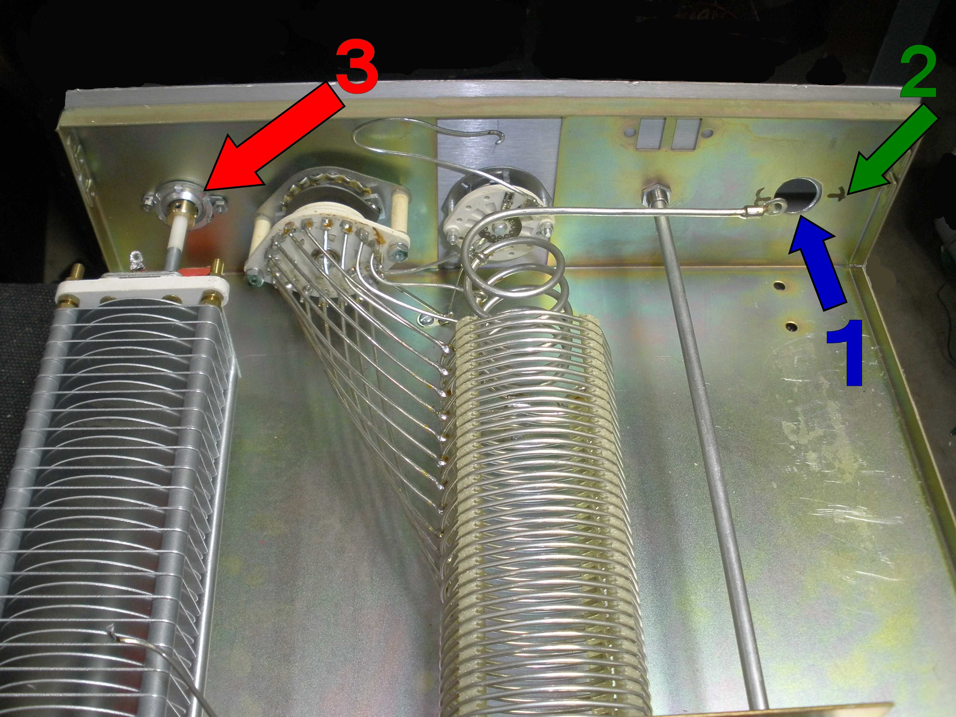
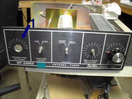
- Punch new holes using a Greenlee punch to clear the front of the Jackson ball drive planetary gear reduction unit. Punch the front panel and the chassis separately. This new large front panel hole is shown as (1) on the photos below. The thickness is too much for the punch to handle both at the same time. This requires careful alignment of the punch to avoid the final holes not aligning properly between the chassis and panel. NOTE: The new Jackson planetary gear drive mounts to the INSIDE surface of the front panel and chassis.
- Mount the Jackson ball drive to the tuning capacitor. Do not lose the set screw, which is inside the plastic bag used to ship the unit. Only one set screw is furnished, and I did not need a second set screw to prevent dial slippage.
- Be careful when handling the capacitors to not break the plastic insulating shaft, which prevents electric shock. If you break the plastic, you will have to install an insulated shaft coupling to provide insulation, since the frame of the capacitor is hot, above ground potential. Due to the short shaft insulator, it will be difficult to find a suitable shaft coupling if you mess this up.
- Assemble the capacitor to its insulator rail and temporarily install the capacitor assembly in the chassis.
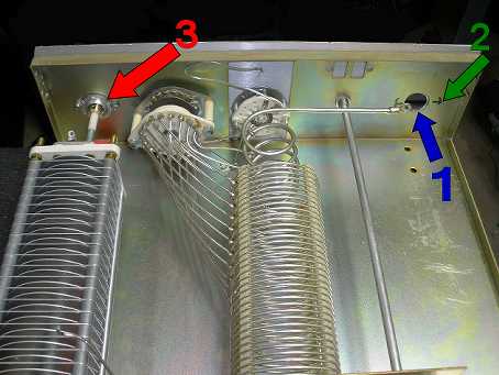
- Mark the mounting holes (2 in the photos below) for the planetary gear ears on the inside of the cabinet, using an automatic center punch. This punch, which does not require a hammer, is available at Harbor Freight. When you push the punch top part, it clicks and makes a mark to start a small drill. Assemble the front panel to the chassis, using the coil and tuner/bypass switches, being careful to align the capacitor access holes. Drill two very small pilot holes from the inside of the chassis, one for each ear of the planetary drive. Finish the drilling for clearance for a 4-40 screw. Keep these holes out on the ears of the drive, so that there is room for the nut.
- Complete the assembly of the capacitor, insulator rail, planetary drive, and screws holding it all together. The assembled unit mounts to the INSIDE of the front panel, as shown by the (3) arrow in the photos below. If you are going to use some hot glue to insulate the counter sunk capacitor mounting screws, this is the time to do it. Another approach would be to drill a fairly large half inch diameter hole in the chassis under the spot where the capacitor mounting screws nearly meet the chassis.
- You may need to "adjust" the hole in the red pointer to align the hole in it with the Jackson planetary drive with a small modeler's file. Use a 2-56 screw to mount the pointer to the Jackson planetary drive. Install the capacitor tuning knob.
- Repeat the process with the right hand capacitor.
- Reinstall all wiring.
- Building a transmatch that covers 160 through 10 Meters is a challenge. The capacitors have to have a maximum capacitance sufficient to function at 160 Meters. This makes it difficult to achieve minimum capacitance values to work at 10 Meters. You may find that the small vertical coil in the front of the cabinet can be adjusted by spreading its top two turns. This may allow better match on 10, 12, 15, AND 17 Meters. Be very careful you do not stress the switch while making this adjustment. Support the connecting wire to the switch with pliers to remove the stress from the ceramic switch.
- Reinstall the balun. If the wires do not reach, you may be able to extend them with bare wire, or simply leave the balun out.
- Using an ohm meter, test the bypass function. Also test for shorts to ground.
- OPTIONAL: I observed that the coax used to wire the Dentron MT-2000A tuner is only RG-58/U. When running higher power, this could be a problem, especially on the output side with a high impedance antenna like an end fed wire. I did not replace it with RG-8/U, because I do not use it that way, and never have had any problems with it. I also did not wish to risk possible damage to the bypass switch during the modifications. You might want to upgrade to better coax while you are in there.
- NOTE: The coax connectors will melt if you use excessive heat. You can remove the nut and take the coax connector out, assemble the new coax to the connector, and reinstall it as an assembly, with the coax all stripped, tinned, and ready to solder to the tuner/bypass switch. You may find that premium grade RG-8/M will do the job for you, and is easier to work with than RG-8/U. Do not cut corners, if you are doing an upgrade. If you do this, it will be a lot easier to do it while the chassis is stripped, before you reinstall the balun and tuning capacitors.
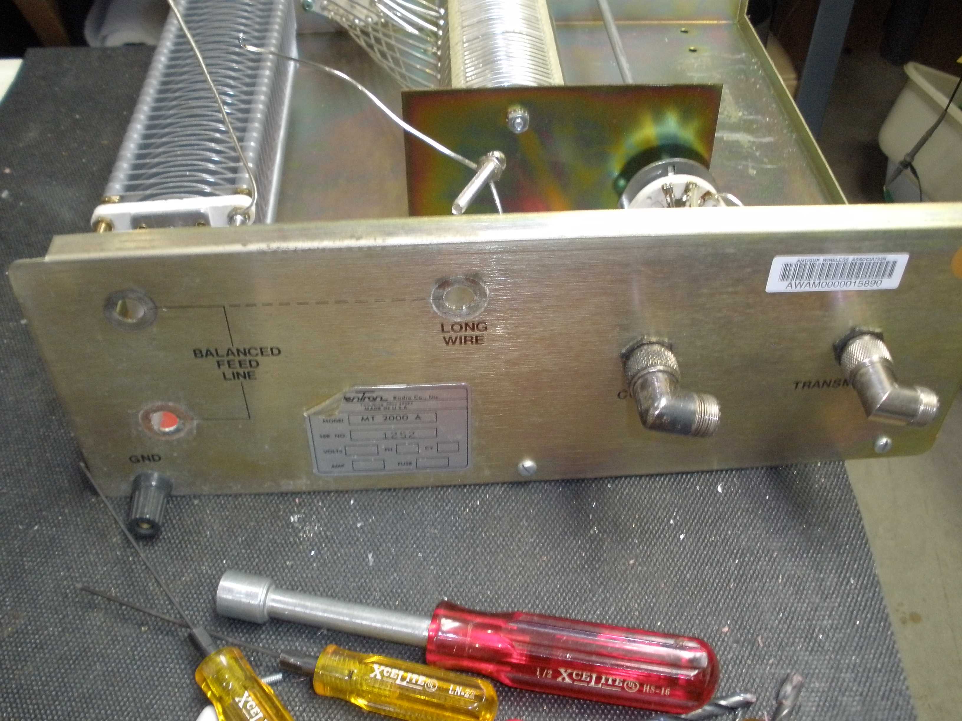
The two photos below show where to place the new holes in the front panel and chassis. Click on a photo to enlarge it.
The photos below show the process and the final product when doing this modification.

|