|
W3GMS, Joe Fell, our amateur forum leader kicked off this session with presentation of this year's contest awards and information about changes to the rules.
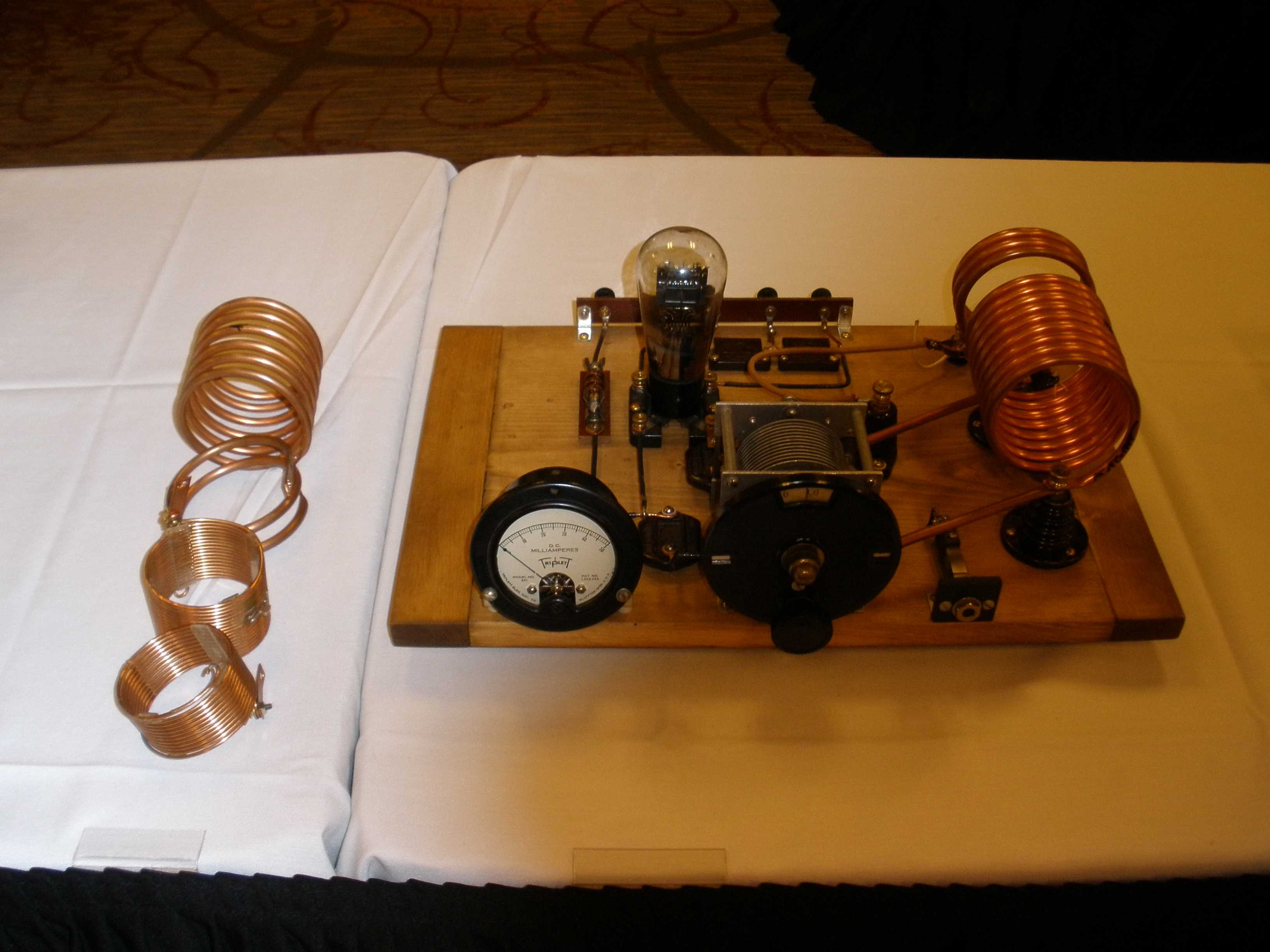
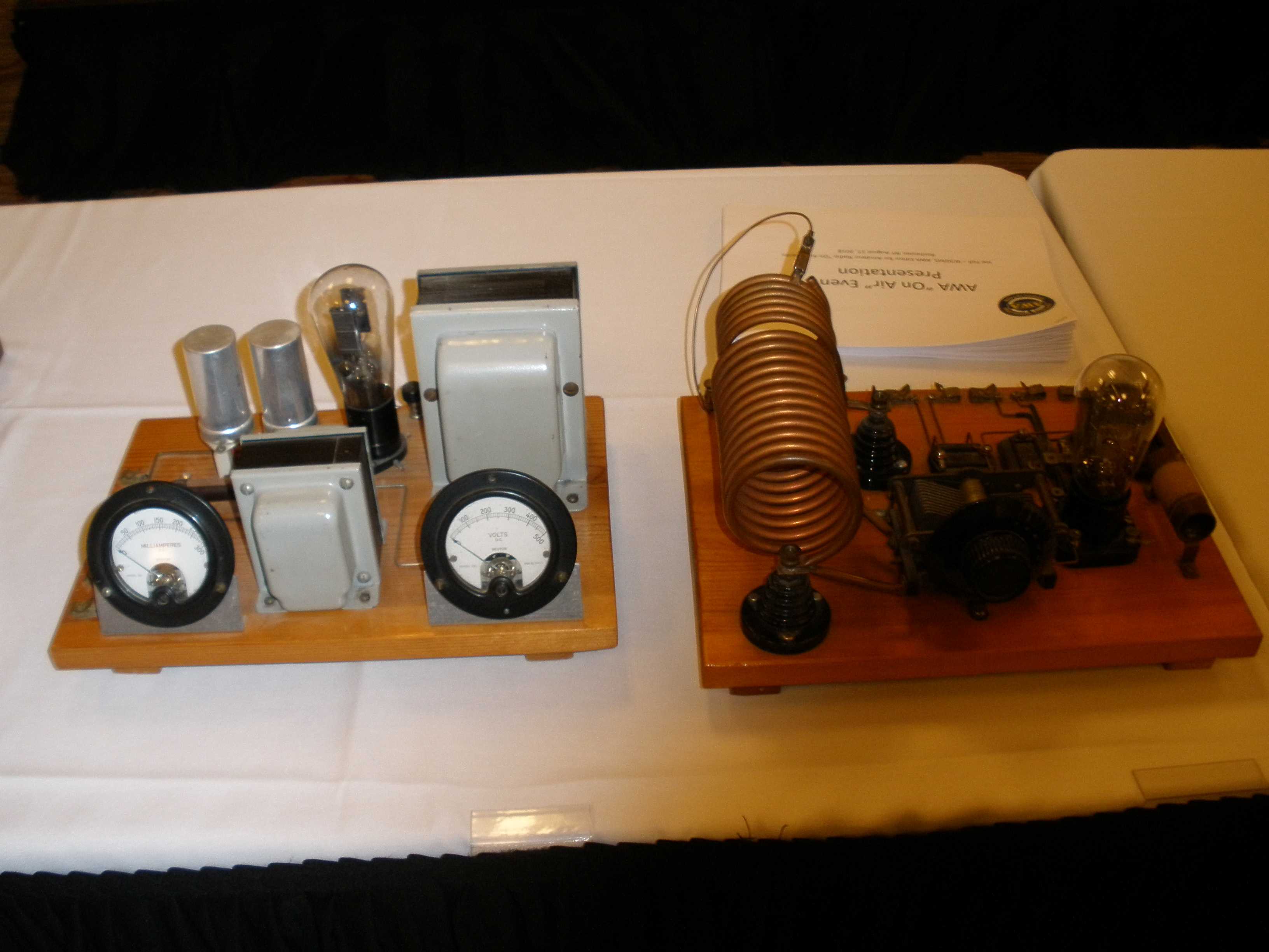
There was some great show and tell, 29 style pine board rigs as well.
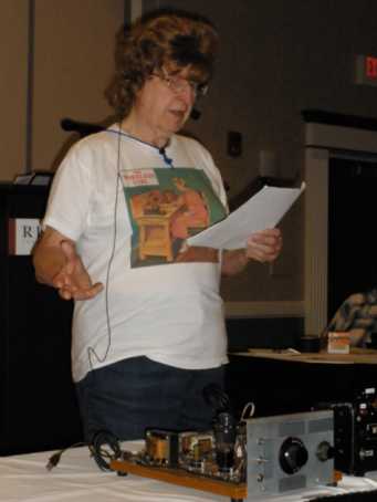
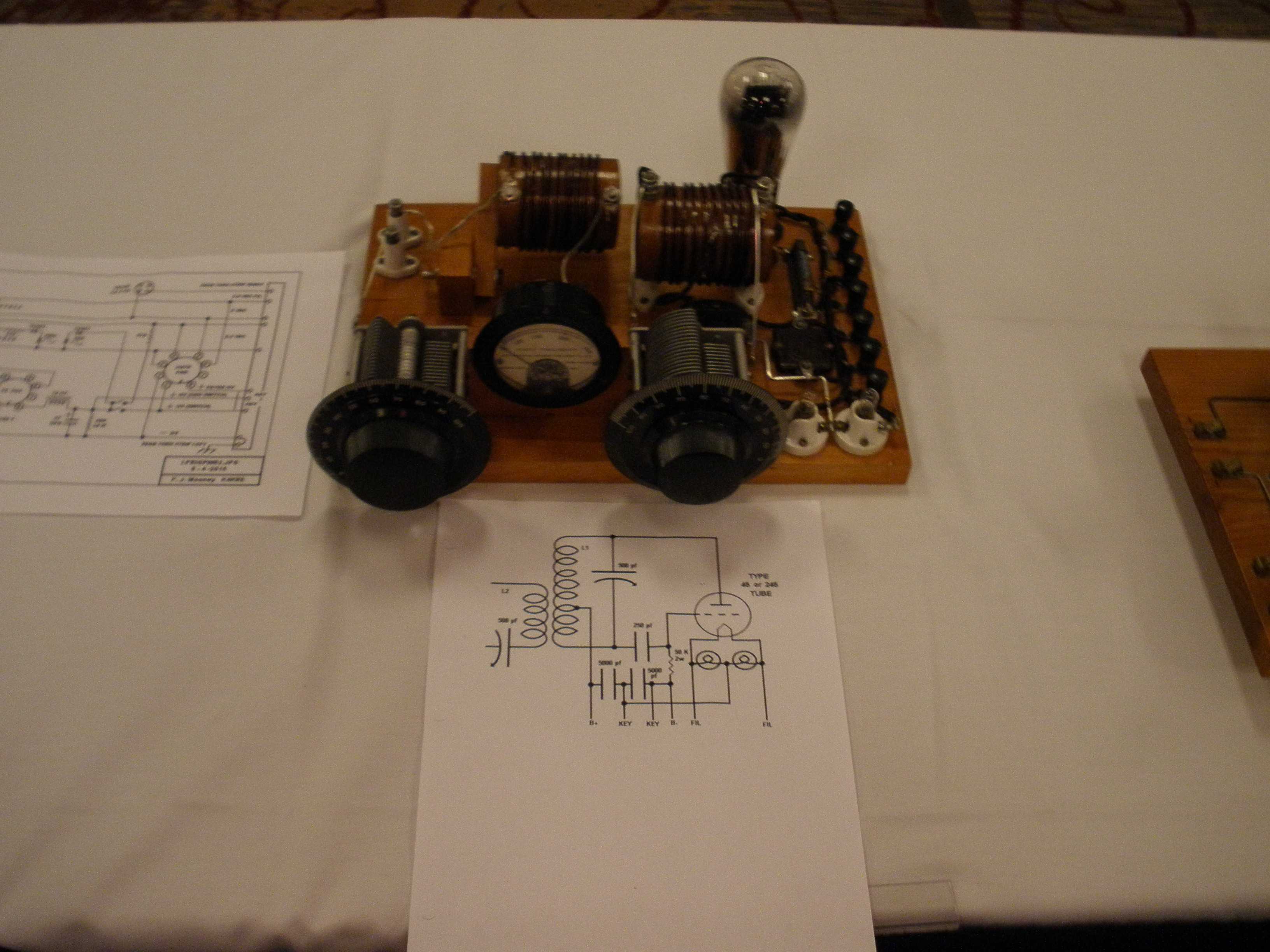
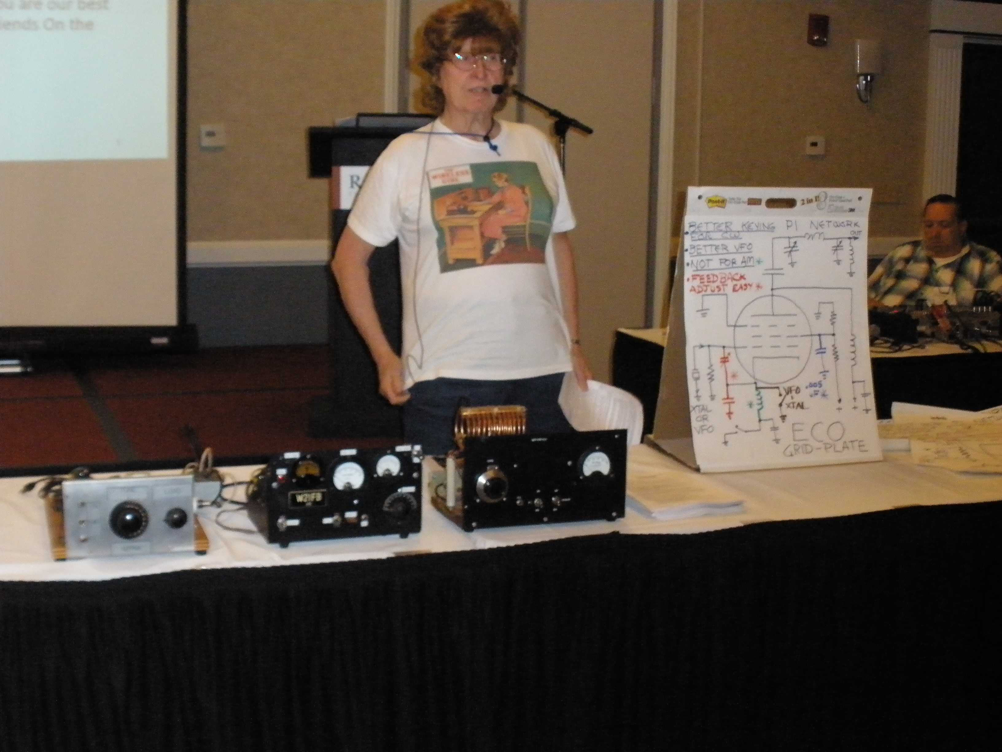
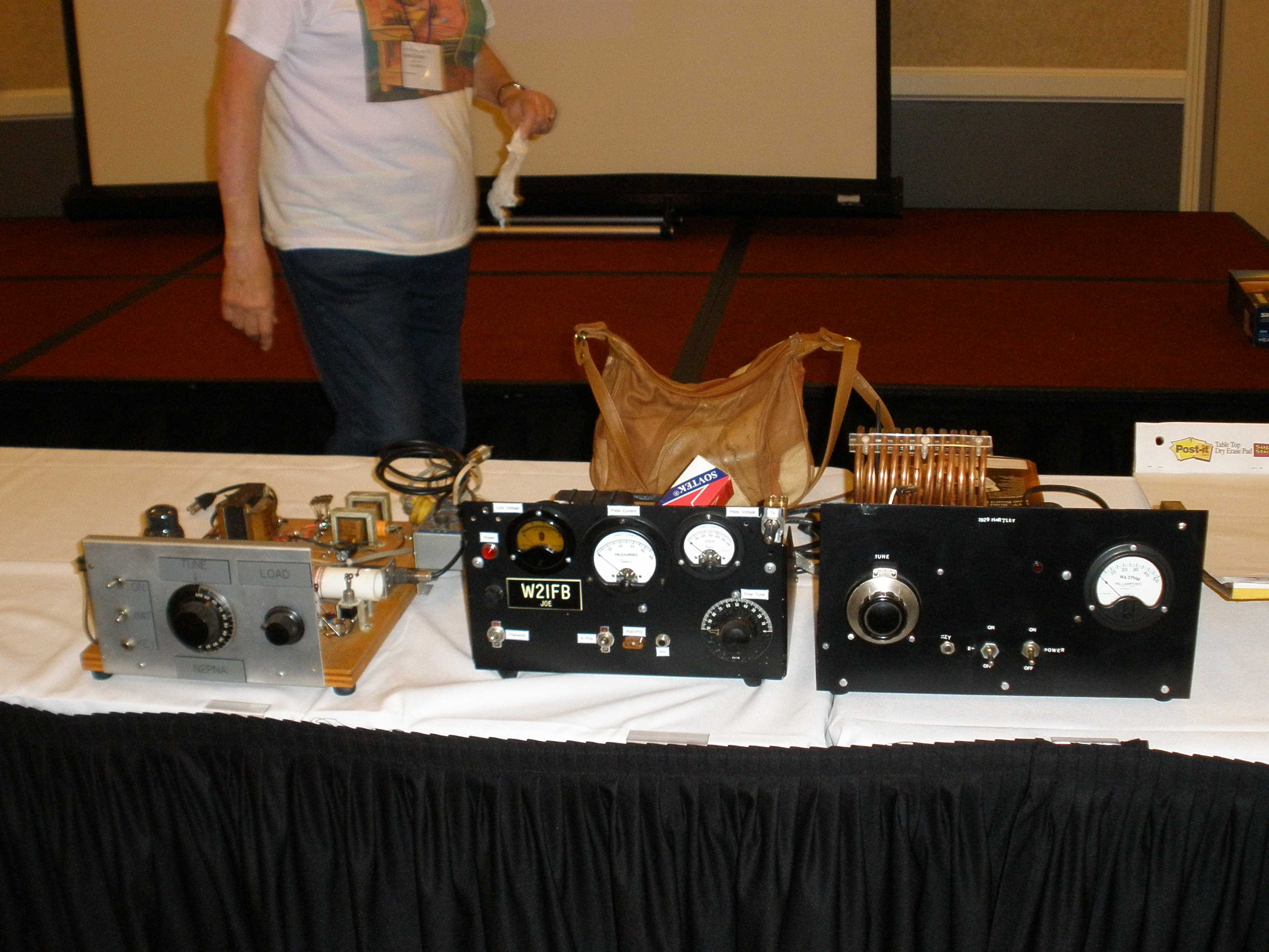
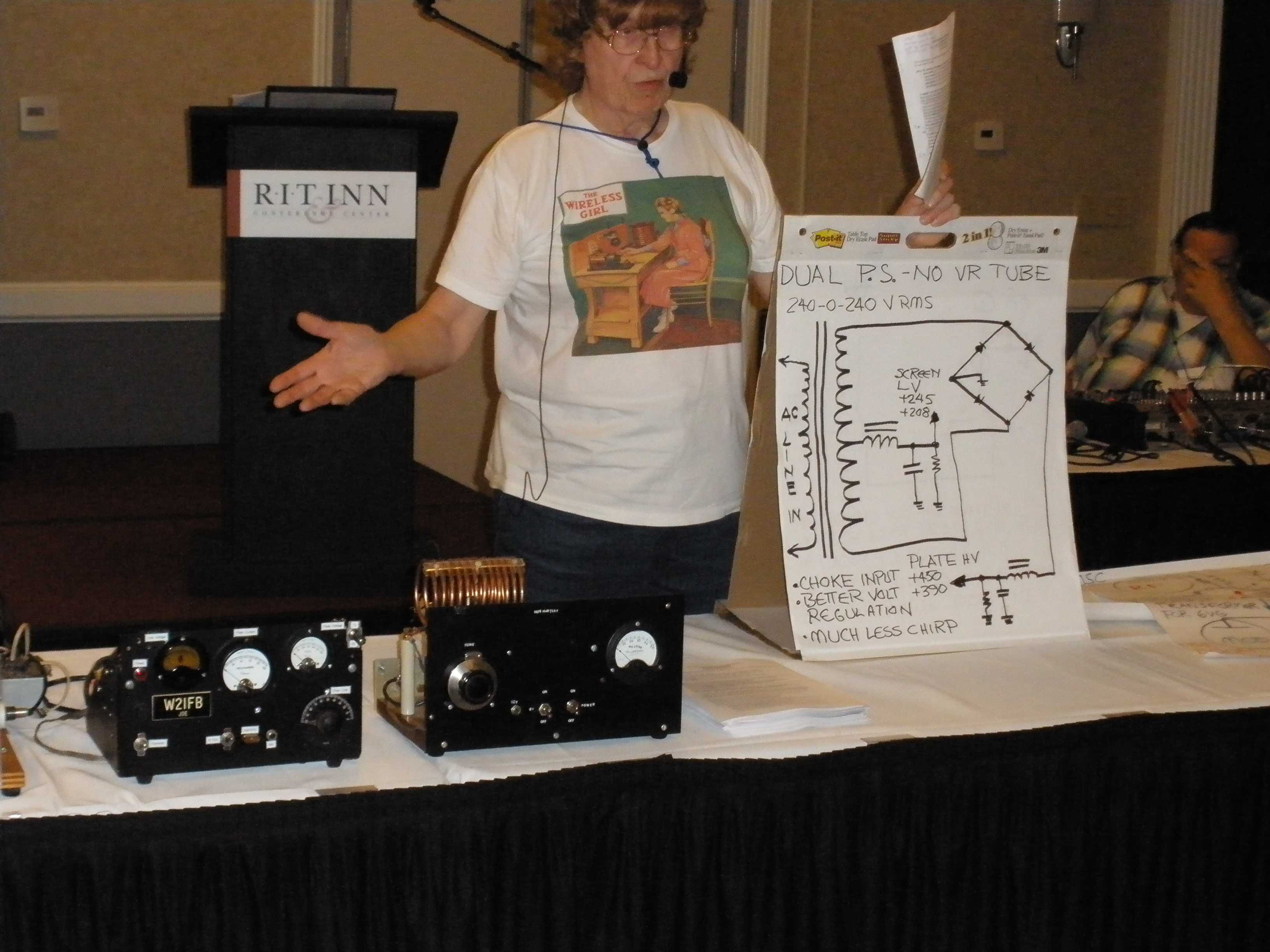
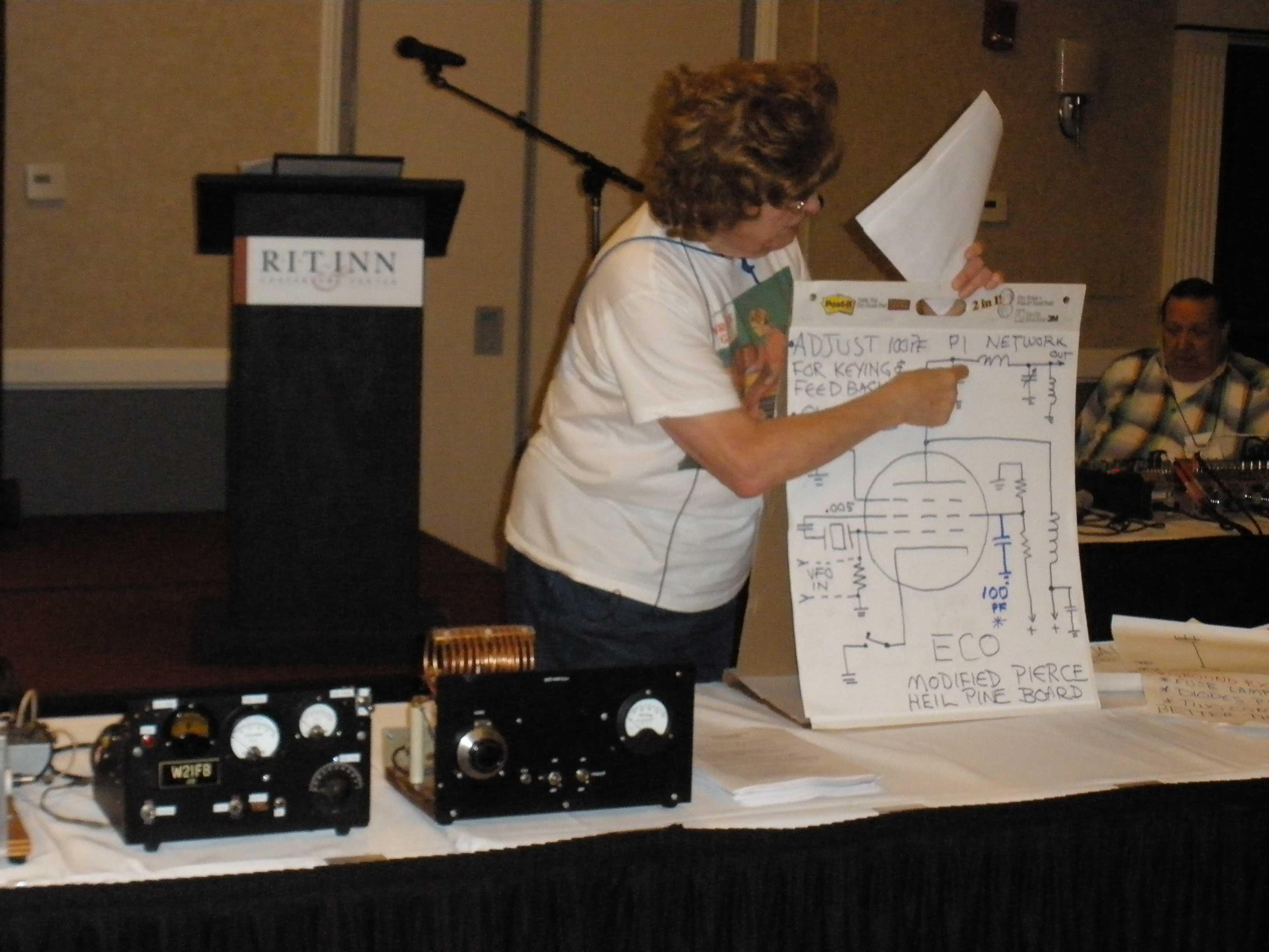
Then I did this presentation. I brought these three rigs, representing the various pine board techniques. Left to right, a 6V6 MOPA rig, a 6AG7-6L6 rig, and a 29 Hartley using a type 24 tube.
This is intended as an introduction to the AWA contests and encouragement to build simple radio gear for use in those contests.
Four AWA contests are for equipment of a certain date of production. Build your home brew transmitter to fit one of these categories:
- Bruce Kelley 160, 80, 40: 1929 or early design, and use early
pre 1929 tubes.
- Linc Cundall 160, 80, 40: Low power, before 1950 (like WW2
surplus rigs) Extra points for OT RX and OT TX, and power levels 25W, 75W, 150W, 150+
- John Rollins 40 & 20: Low power, before 1960, same scoring style as Linc Cundall
- AM QSO party, any gear, NEW OUTPUT CLASSES: less than 25 W, 25 - 100 W, 100 W+
USE PINE BOARD CONSTRUCTION FOR EASY ASSEMBLY OF YOUR HOME BREW CW OR AM RIG
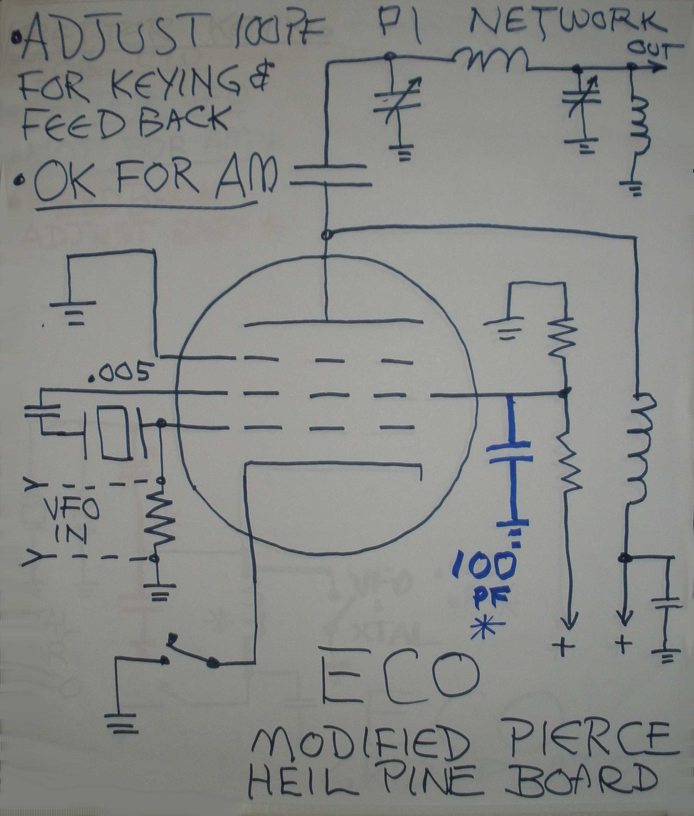
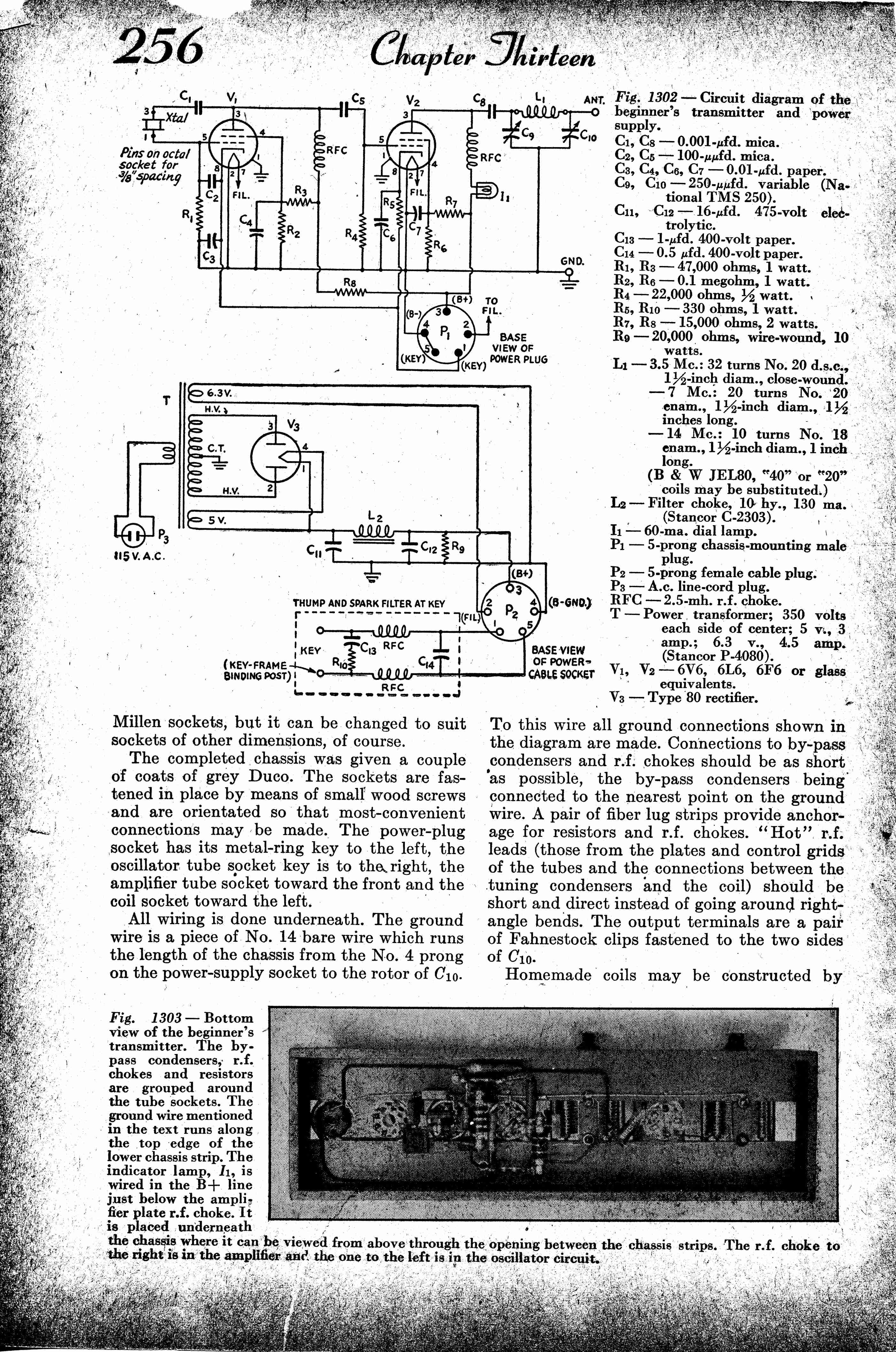
Complete 5 watt AM/CW rig: Bob Heil "Pine Board Project" QST January 2018, more detail at:
Complete Parts Kit (rig $52, power supply $90) but can improvise from your own parts:
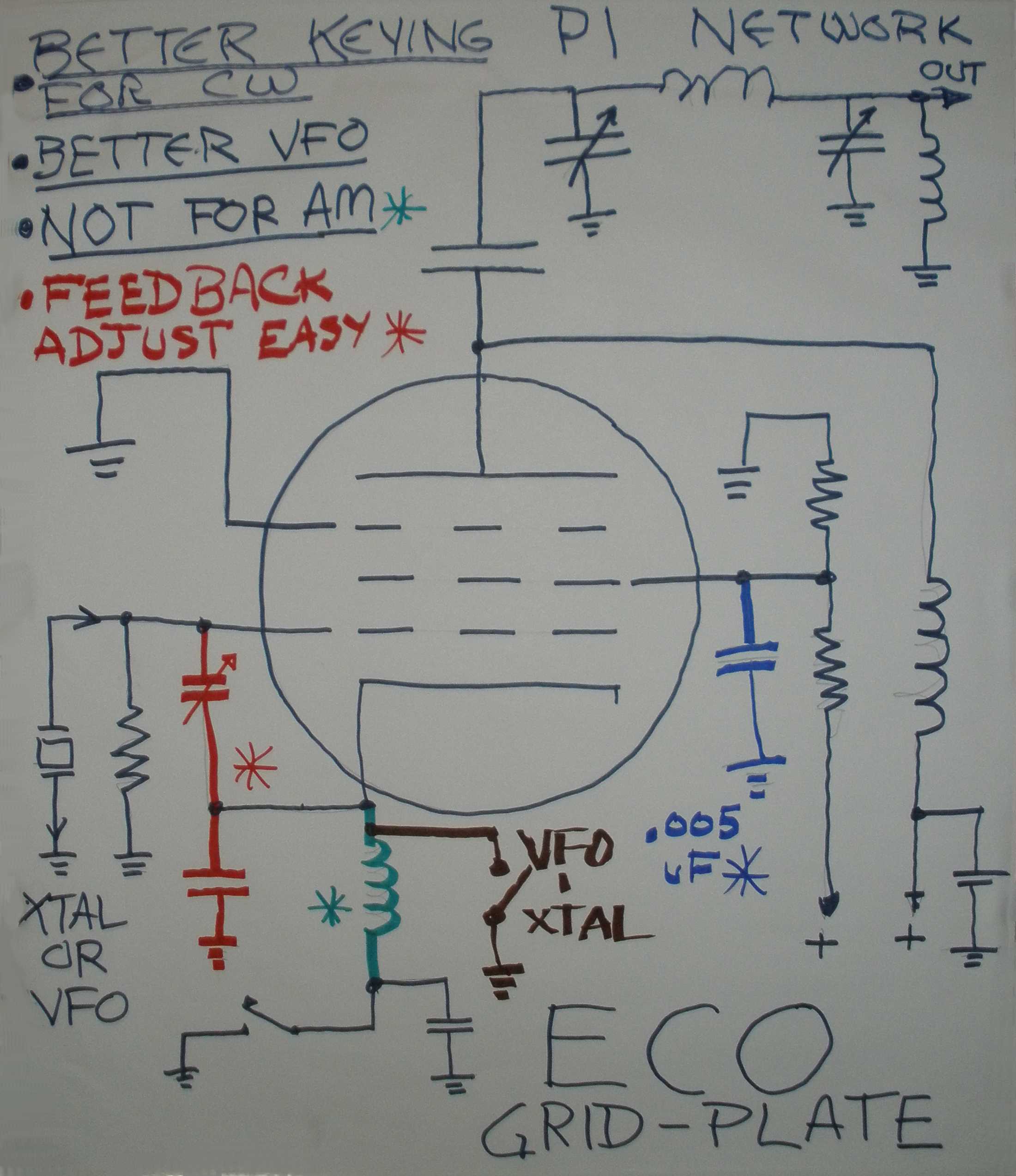
Save by building only for CW. (Must disconnect Heising choke or mod transformer in Pine Board for CW and feed B+ to RF stage direct, or keying waveform is bad, due to inductance ringing).
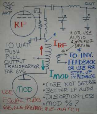
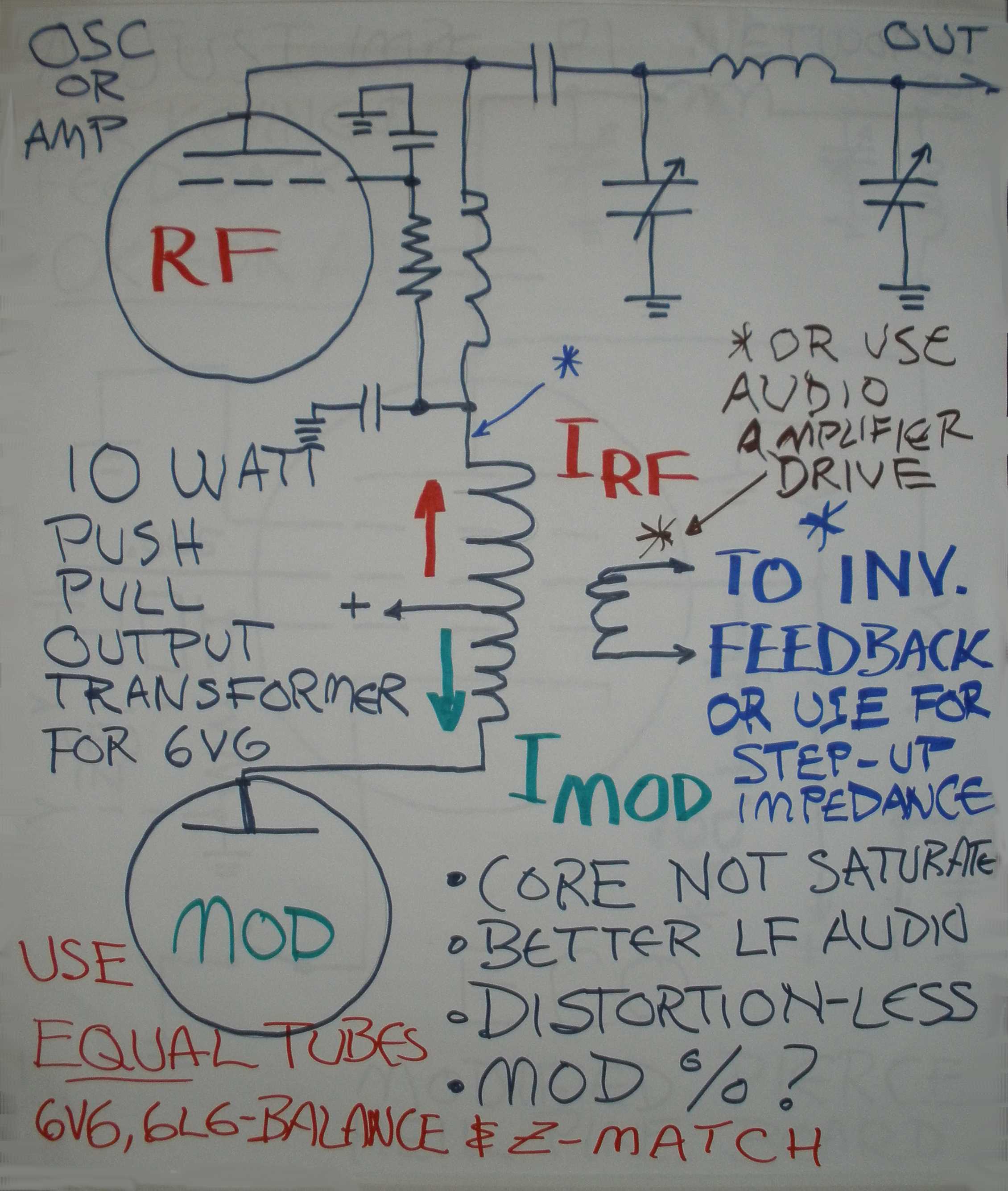
Why a push pull output transformer could be a better choice for the modulation rather than a heising choke. Comes from March 1945 QST page 56, WW2 WERS techniques. Note that a common push pull audio output transformer is cheap and available compared to a modulation transformer. The red and green arrows show that the tube current for the RF stage and the modulator is balanced to cancel out the flux in the core of the audio transformer, to prevent saturation. The result is better efficiency and frequency response. Possibly the speaker output windings could be used for inverse feedback, or connected as boost windings in the RF side to get more modulation. With a single ended audio transformer, you could eliminate the Heising modulator tube and drive the speaker winding with a small audio PA system amplifier.
Common Methods: Buss Wire, sheet metal below board for ground plane, flat top of sheet metal on wooden side rails. The "rail" construction was popular. No sheet metal bending required.
Multiple modular pine boards for RF stages, audio stages, power supply make for easy trouble shooting.
Could Use the "kitted parts" for Bob Heil's project OK.
While crystal control is encouraged, a SEPARATE VFO can be home brew or commercial like VF-1 or Johnson 122. Solid state synthesized VFO like N3ZI also OK for the AM contest.
SEPARATE Power supply can be on metal chassis, and employ solid state rectifiers. OPTIONAL to build it on a pine board.
SEPARATE Modulator can be on metal chassis, commercial modulator OK like Eico 730. OPTIONAL to build it on a pine board. Reverse connected Hi Fi output transformer driven by solid state amplifier also allowed, but tube type modulators encouraged.
EXAMPLES OF TWO OF MY PINE BOARDS:
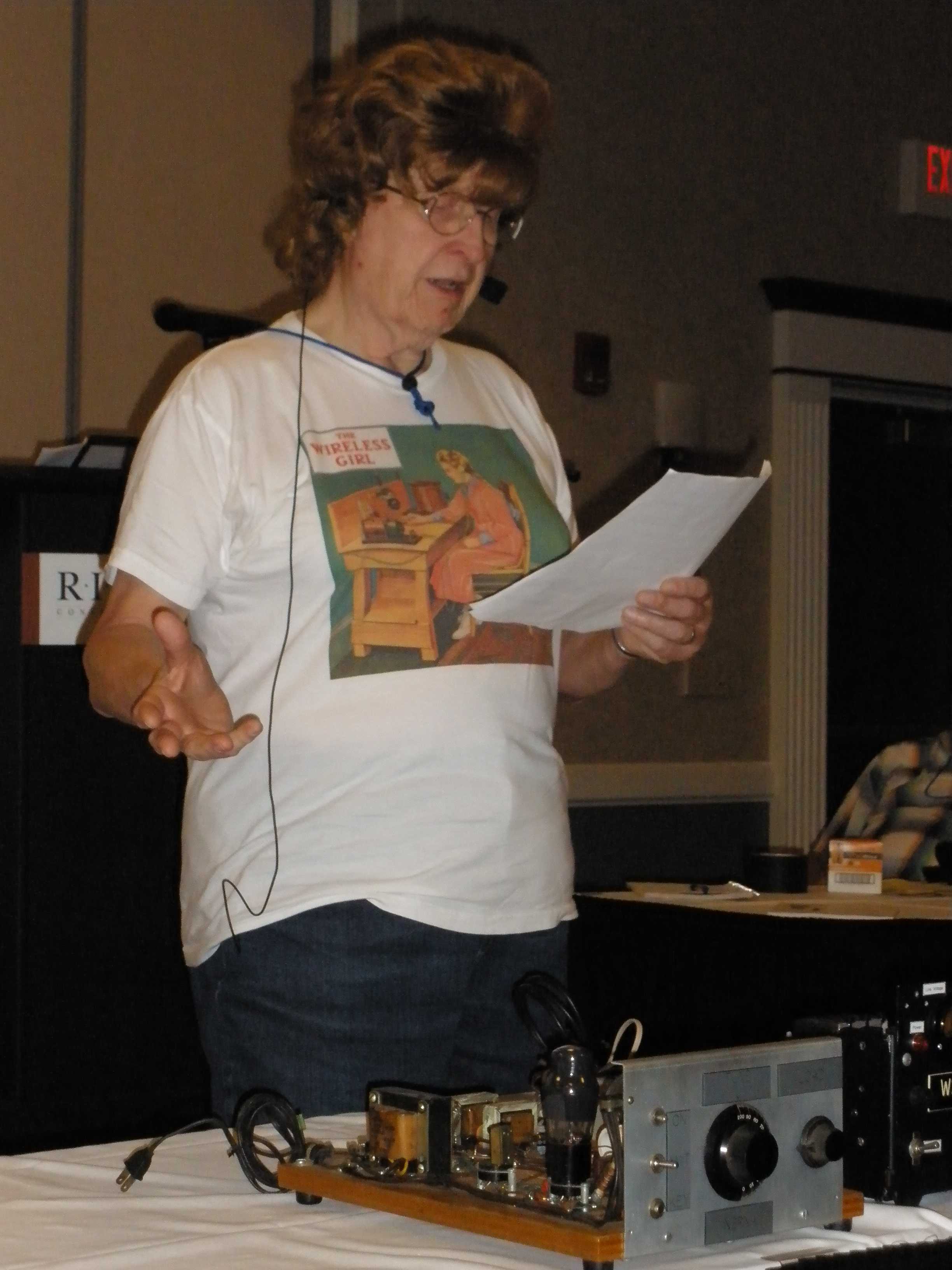
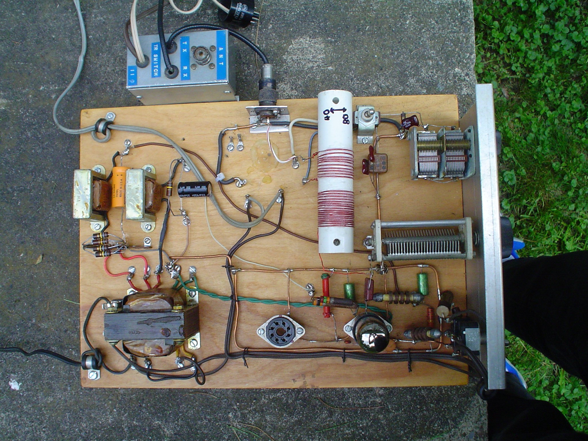
This one was built by my son at age 11 from 1944 handbook.6V6 Oscillator rig for 80 or 40 meters, about 5 to 8 Watts output:
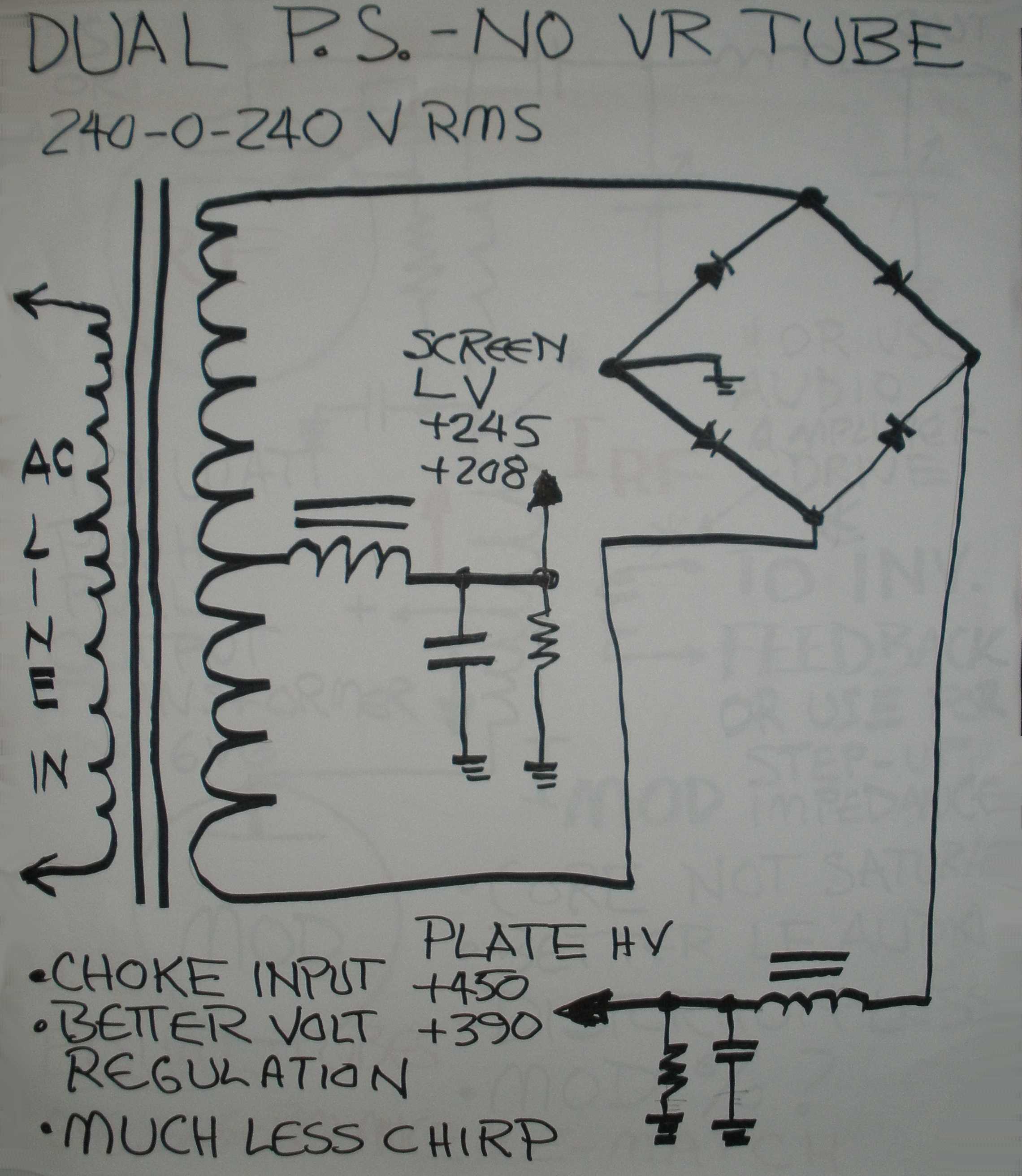
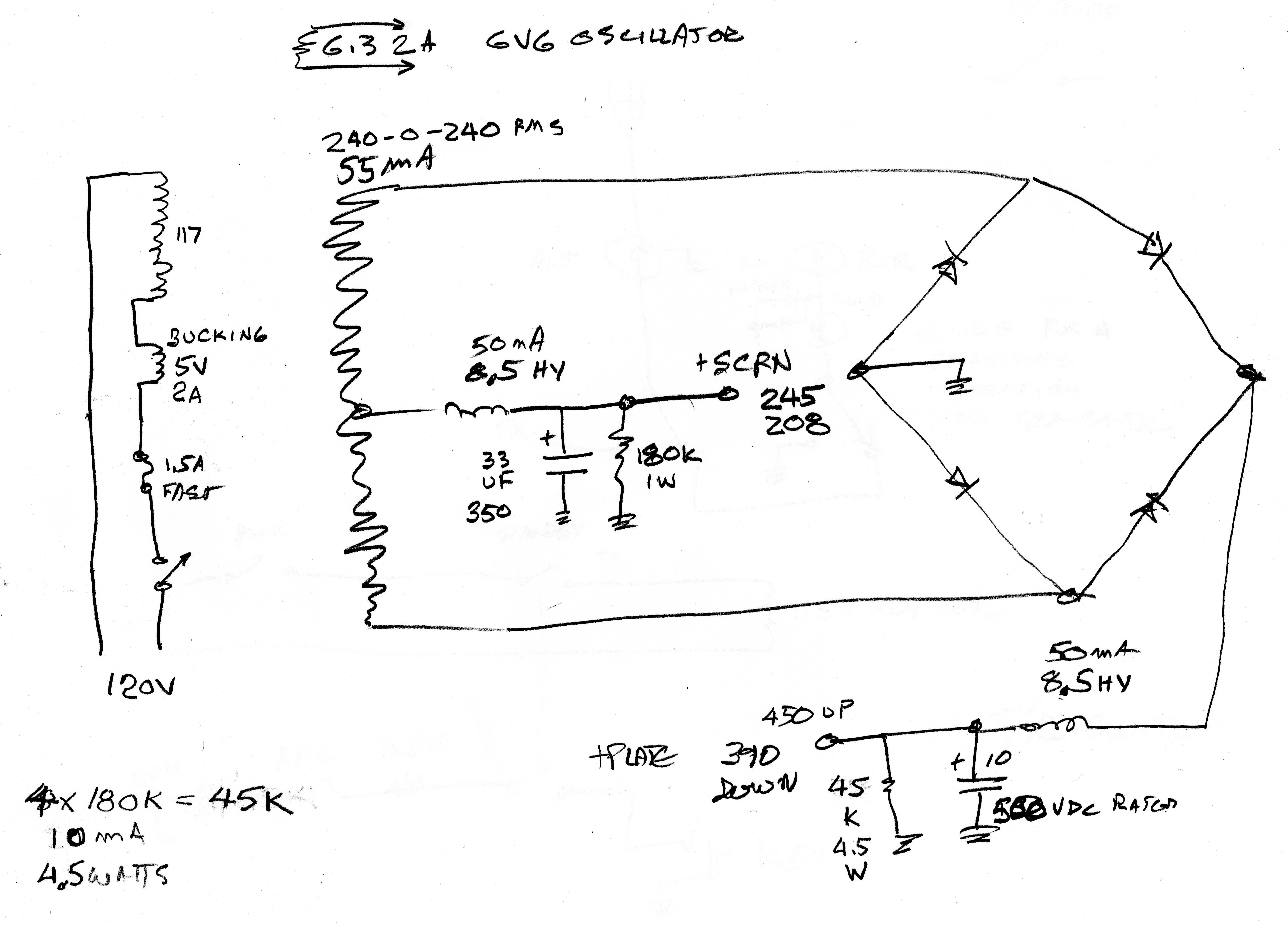
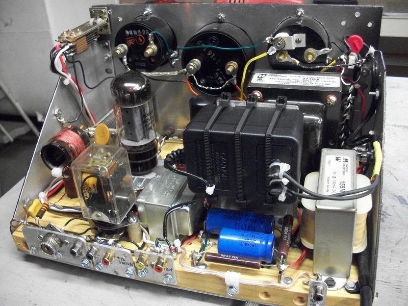
My trick to avoid a VR tube and still have low chirp CW; (Use dual output "economy" power supply):
Feeding the oscillator tube screen from a stiff voltage source instead of a dropping resistor fed from the high B+ increases stability and reduces chirp caused by poor voltage regulation. It eliminates the need for a VR tube. Also, use of choke input filtering rather than capacitor input increases power supply regulation. Voltages shown are Key UP and Key DOWN, demonstrating voltage variations.
https://wireless-girl.com/Projects/CWRigs/mopaPS.jpg
http://wireless-girl.com/Projects/CWRigs/Homebrew6V6.html
https://wireless-girl.com/Projects/CWRigs/DSC00002.JPG
This one was built by a friend with my help as his very first homebrew.
6AG7-6L6 rig for 80 or 40 meters, 15 to 20 Watts output:
https://http://wireless-girl.com/Projects/CWRigs/Homebrew6L6.html
https://wireless-girl.com/Projects/CWRigs/6L6_RIG_A.jpg
https://wireless-girl.com/Projects/CWRigs/6L6_RIG_B.jpg
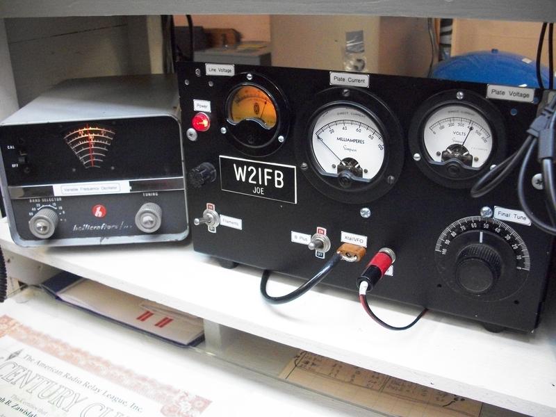
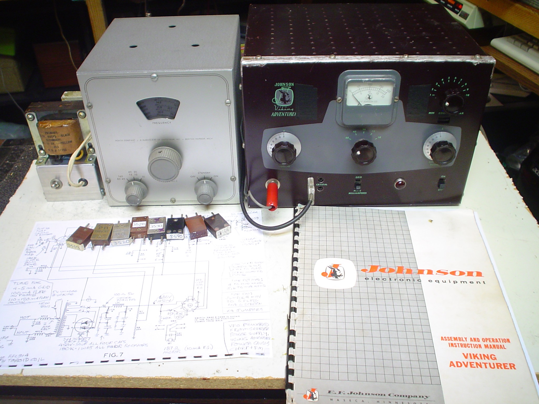
Simple Johnson Adventurer rig: 6AG7-807 (up to 35 W Output).
http://wireless-girl.com/Projects/AMTransmitters/JohnsonAdventurer/AdventurerVFO2.jpg
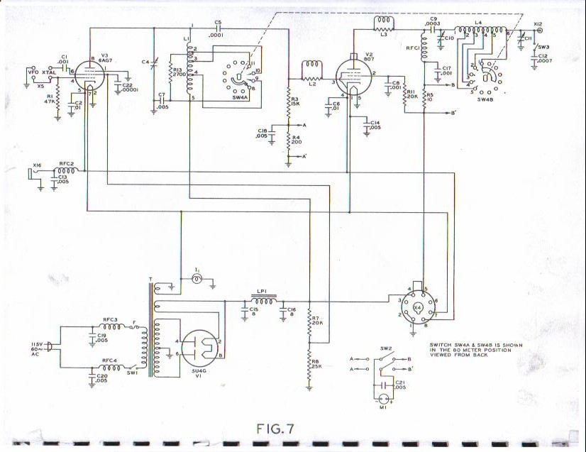
http://wireless-girl.com/Projects/AMTransmitters/JohnsonAdventurer/ADVENTURERschematic.jpg
I won the Rollins contest with this rig. This design is simple enough you could home brew it and use it in the Linc Cundall contest, since the design dates before 1950.
YOU CAN DO IT TOO! Or mentor someone else to do it, be an Elmer.
DETAILS FOR YOUR OWN MODIFICATIONS AND DESIGNS:
SUGGESTED NEW REQUIREMENTS FOR AM PINE BOARD CLASS (3 points per QSO)
MAXIMUM 25 WATTS POWER OUTPUT. (Other AWA events rated by INPUT, AM is by OUTPUT.)
- MAXIMUM 25 WATTS POWER OUT. Nothing about tube manufacture date in the AM contest. Encourages QRP AM. Possible common tubes like 6V6, 6L6, 807, even 6146 at lower plate voltage. Also encourages rigs like DX-60 or modern transceivers to participate.
USE YOUR PINE BOARD RIG IN OTHER AWA CONTESTS:
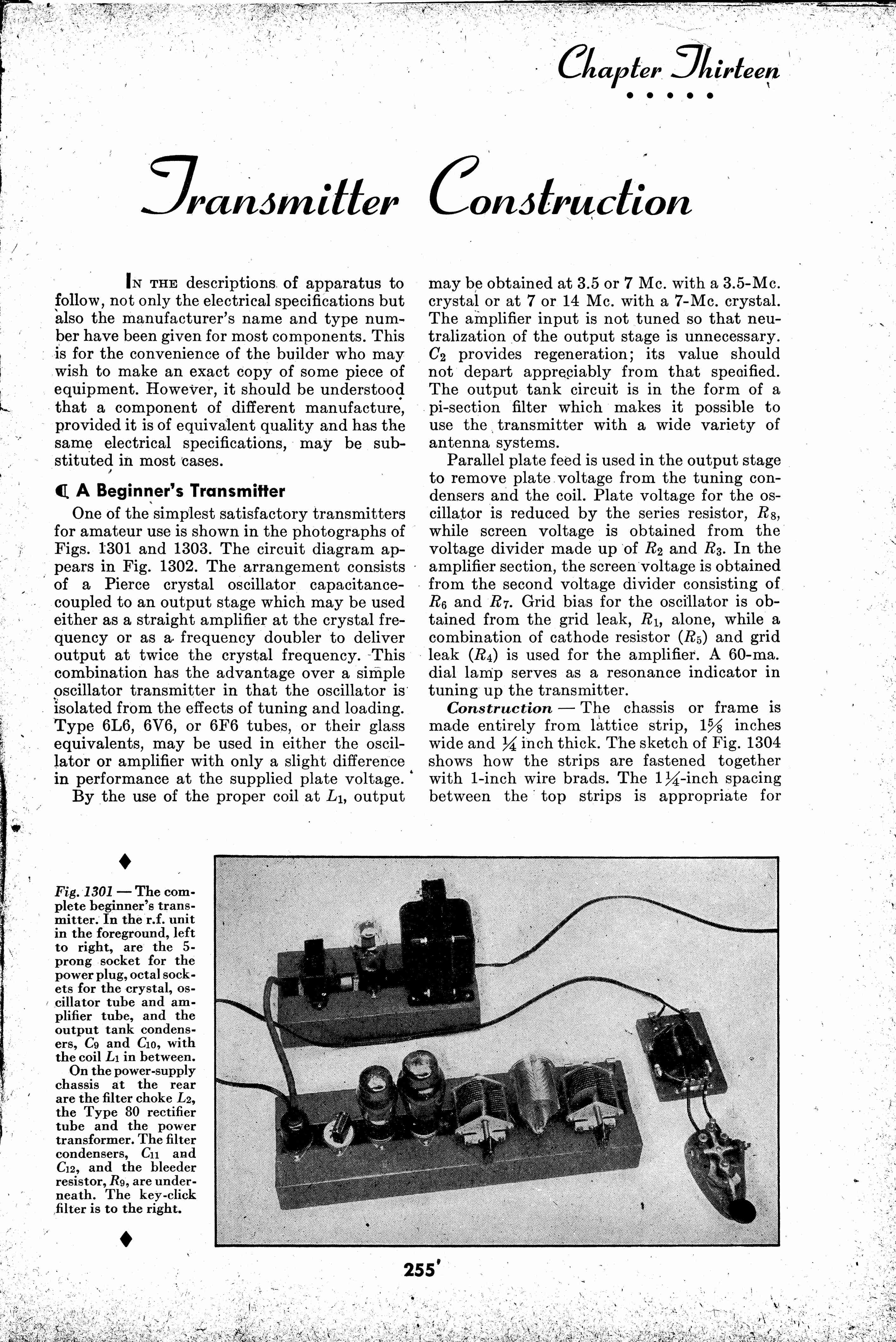
The 807 (1937), 2E26 (1947), 6L6 (1936), 6V6/VT-107 (1936), 7C5 (1939), 6F6, (1935), 6AG7 (1939 RCA manual), and 6AC7/1852 (1939 for oscillator or VFO use), 41 (1928, similar to 6K6), 42 (1932, similar to 6F6), 45 (1929, similar to 2A3 or VT-52) were all available prior to 1950. (The 6146 came later in January 1952.) I have found Pi networks for transmitter outputs (rather than the traditional link coupling) explained and used in Radio Handbook (West Coast) editions 11 & 12 for 1947 and 1949, though that handbook was addressed to an audience with better than average technical skills. The Pi network has adjustable coupling for more output; the popular link output coils had to be experimented with multiple times to get full output. That is why in more modern designs, link coupling fell out of favor. Bill Orr was always a leader. You could use your pine board rig on CW for the Rollins and Linc Cundall as well. The VFO would have to be home brewed or a Viking 122 VFO (1949), Meisner Signal Shifter (pre-1950) for the Linc Cundall.
Click on the images above to enlarge them. The above construction article is for a complete transmitter using Pi Network output published in 1947. It should work on 160, 80, 40, and 30 meters. The 6L6 is rated for full output up to 10 MHz, and becomes increasingly difficult to stabilize as frequency goes up. One of the Radio Handbooks by Bill Orr shows a 6L6 transmitter operating on 6 meters. The Harvey Wells bandmaster pushes an 807 to 2 meters, but these are examples of doing something just to prove you can; the output is low and the techniques to achieve it are extreme. The AT-1 DOUBLES in the final PA above 80 meters, and manages to run a 6L6 on 10 meters, but it has a tuned circuit between the 6AG7 and the 6L6 PA.
Builders should use caution when doubling 80 meter crystals for 40 meter output without a parallel tuned circuit somewhere in the design, since a Pi Network is a LOW PASS FILTER. Some "subharmonics" could pass through, since there is no parallel tuned circuit to eliminate them. Placing such a tuned circuit in the grid of the 6L6 PA invites self oscillation as a TPTG oscillator; the 6L6 is not well screened. This problem could be addressed by choice of an 807 instead of a 6L6, which would require other circuit changes. I have seen neutralization circuits much older than this 1947 article, but leave it to you as to its efficacy with a 6L6.
Please check out my other pages, Subharmonics in Vintage Equipment and Neutralize Your Transmitter!, for more pertinant information. NOTE: A parallel tuned antenna coupler like the EFJ matchbox also helps with both subharmonics and harmonic supression. Directly coupling a rig like this without an antenna tuner into an end fed wire or an antenna with multiband resonances should involve careful thought, but it is successful in many instances.
TECHNICAL HANDOUTS
QST March 1945 Page 56: Use of Push Pull Hi Fi Transformer for Modulation Transformer (1 sheet)
Complete RF 6L6 Class C RF specs for AM, CW, discussion
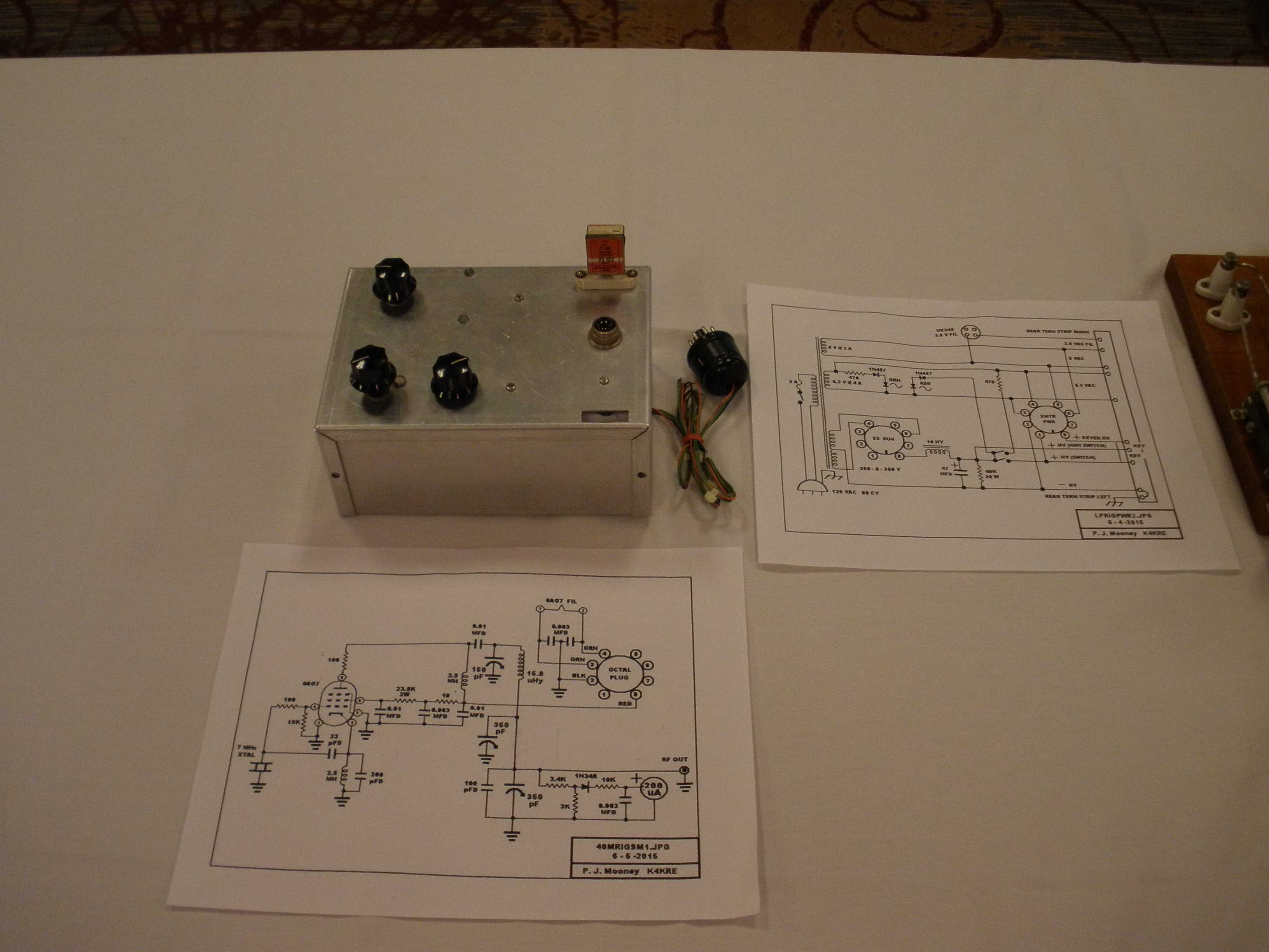
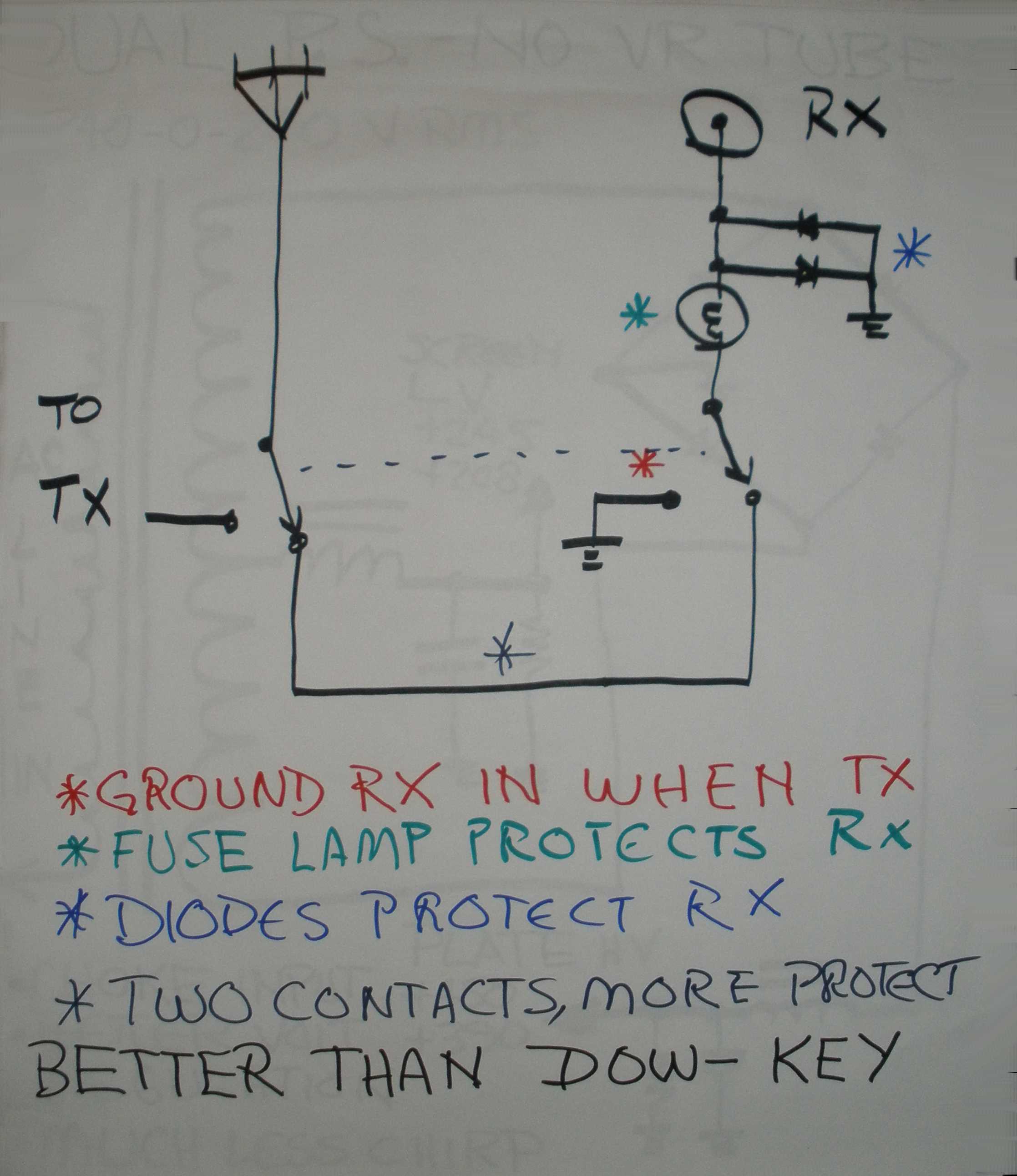
3 Schematics of AB2RA rig, 6V6 with dual output power supply for chirp reduction and receiver protection T/R switch (3 sheets)
http://wireless-girl.com/Projects/CWRigs/Homebrew6V6.html
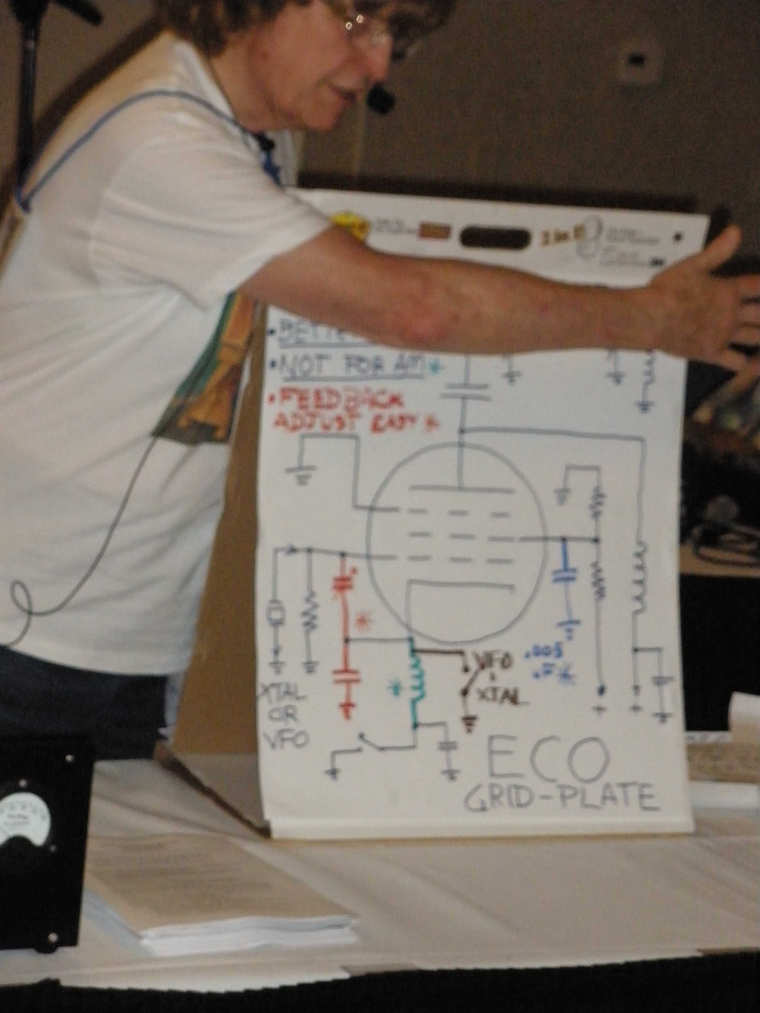
6AG7 as RF amp instead of oscillator: https://faculty.frostburg.edu/phys/latta/ee/6ag7amp/schematic/6ag7schematicfull.jpg (1 sheet)
2 stage 6L6 rig, with Pi Network Output: 11th edition 1947 Radio Handbook (2 sheets)
3 pages, outline of presentation, with internet links.
Nice Pine board style 6AG7 and two 807s CW rig:
https://www.qsl.net/wd8das/dream.html
NOTE: schematic shows plate current meter to ground, may pin as shown. May need screen resistors in 807 lead for stability and raise low B+ to 300 V for more output. Needs data for other bands and mods for phone. Needs safety RF choke to ground on output. Beware of coupling between grid and plate coils of 807. Nice example of pine board construction though.
Nice complete 6AG7 and single 807 CW rig in metal cabinet, but could be done pine board style:
https://www.qsl.net/k5dh/6ag7_807.html
Make sure RFC2 is smaller or eliminated compared to L2 to avoid LF parasitics. Could also eliminate blocking condenser C5 and RFC2 and feed B+ to 6AG7 thru L1. But plug in coils might invite shock hazard in that case, so a band switching coil would be required. Good safety considerations in his design. Includes RFC for safety across the antenna connector. Includes parasitic resistors on control grid and screen grid. Includes spot switch. Includes grid meter shunt resistor, but does not show grid meter in schematic. Shows how to use VFO with this rig. Could get less chirp in XTAL control, if a voltage divider design is used in screen grid of 6AG7 to stabilize. Excellent examples of several important design considerations. Can use Heathkit HP-23 power supply (HW-101 or SB-101) to save construction of power supply, nice touch.
VISUAL DISPLAYS
- QST magazine with Pine Board
- 6V6 Pine Board Oscillator 5 to 8 watts out rig
- 6AG7-6L6 Pine Board two stage 18 watts out rig
- 24 tube bread board 1929 style rig
- Adventurer
- Contest Award Plaque for Adventurer and Rollins contest
|