|
 Many connector installation tutorials use a ruler with inches or centimeters to describe where to cut and strip the coax.
I just use the actual connector because its at hand and easier to visualize. This is proven method I have used for decades.
Bill Orr, W6SAI, uses a tubing cutter such as the type used to cut copper water supply line to cut the insulation jacket.
If you decide to try this, obtain a brand new sharp cutter and use it only for this purpose; if you do plumbing work, get a separate one for that use.
I have become accustomed to using a knife.
Many connector installation tutorials use a ruler with inches or centimeters to describe where to cut and strip the coax.
I just use the actual connector because its at hand and easier to visualize. This is proven method I have used for decades.
Bill Orr, W6SAI, uses a tubing cutter such as the type used to cut copper water supply line to cut the insulation jacket.
If you decide to try this, obtain a brand new sharp cutter and use it only for this purpose; if you do plumbing work, get a separate one for that use.
I have become accustomed to using a knife.
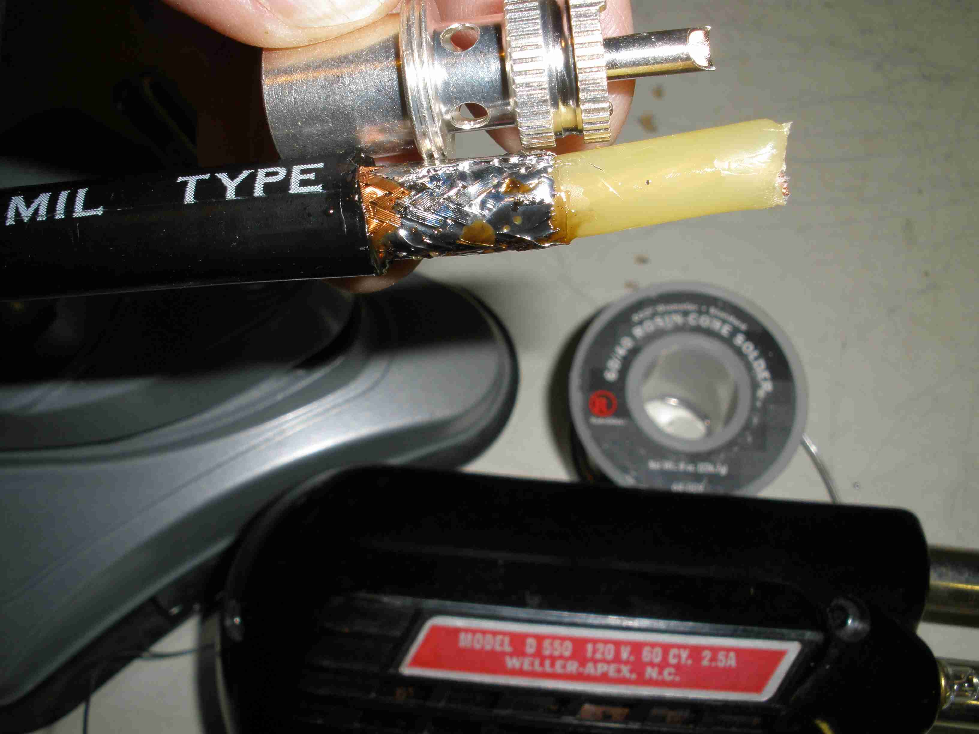
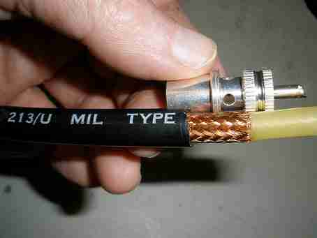
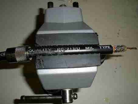
- First, determine where the braid should end on the right hand side,
and cut through both the jacket AND the braid. Do NOT cut thru the center insulator yet.
Also do NOT cut the outer jacket all the way through at the left side exposing the braid as shown in the photo.
After making the first cut, remove the braid and jacket at that point. This makes a nice clean edge of the braid and prevents loose indvidual strands from shorting the connector later.
Try very hard not to disturb the weave of the braid.
- Next make a cut, being certain NOT to cut all the way through the jacket to the braid.
Slightly bend the coax to break the jacket piece you are removing free from the rest of the coax.
- You can make a shallow cut from left to right to make it easier to remove the jacket.
With a sharp wire cutter, pull the jacket only up to start tearing it along the left to right cut, till it goes all the way to the left.
Carefully remove the piece of the jacket; do not disturb the weave of the braid as shown.
- The goal is to have about 1/4 inch of the jacket inside the coax connector once it is screwed on.
If this particular cable is to be a long length that hangs from a dipole center insulator without any strain relief, you might want to increase that to 3/8 inch for a little better grip.
Also, note the braid MUST go just past the solder holes in the connector, so you can solder them later. Leave the center insulator preparation til later, to avoid disturbing the braid weave.
Now you are ready to tin the braid.
 I should mention something first about using only quality materials. I do not use crimped connectors; I am old school.
I bought some commercial patch cables from a well known supplier which used crimped construction.
Several failed, and I threw out the whole lot and replaced them using the techniques shown here.
I use flux sparingly to make the soldering go faster and ensure full wetting of the solder for a proper joint.
This is important to avoid melting the coax insulation. Foam insulation can melt and contaminate the solder joint.
The classic solid center conductor insulator shown here is more resistant to that problem. Use a Weller Soldering Gun with 325 watt rating as shown in the photos.
Smaller irons take longer to achieve proper heat, and also melt the center insulator. Use only quality 60/40 tin/lead solder, not the newer lead free solder.
You will get defective solder joints, and dramatically shorten the life of your solder tip due to the corrosive nature of lead free solder.
Use only Amphenol teflon insulated coax connectors. Even Amphenol has connectors which have insulation which is flat across the surface; these result in shorts in about 20% of the cases.
The correct style has an indented ring around the junction of the insulator to the body, as viewed from the pin end of the connector.
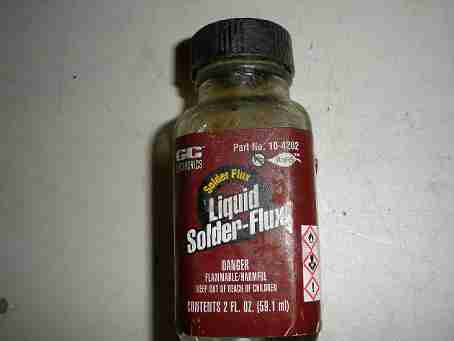
I use brand of flux shown in the photo because its very runny and you can apply it very sparingly.
I should mention something first about using only quality materials. I do not use crimped connectors; I am old school.
I bought some commercial patch cables from a well known supplier which used crimped construction.
Several failed, and I threw out the whole lot and replaced them using the techniques shown here.
I use flux sparingly to make the soldering go faster and ensure full wetting of the solder for a proper joint.
This is important to avoid melting the coax insulation. Foam insulation can melt and contaminate the solder joint.
The classic solid center conductor insulator shown here is more resistant to that problem. Use a Weller Soldering Gun with 325 watt rating as shown in the photos.
Smaller irons take longer to achieve proper heat, and also melt the center insulator. Use only quality 60/40 tin/lead solder, not the newer lead free solder.
You will get defective solder joints, and dramatically shorten the life of your solder tip due to the corrosive nature of lead free solder.
Use only Amphenol teflon insulated coax connectors. Even Amphenol has connectors which have insulation which is flat across the surface; these result in shorts in about 20% of the cases.
The correct style has an indented ring around the junction of the insulator to the body, as viewed from the pin end of the connector.
I use brand of flux shown in the photo because its very runny and you can apply it very sparingly.
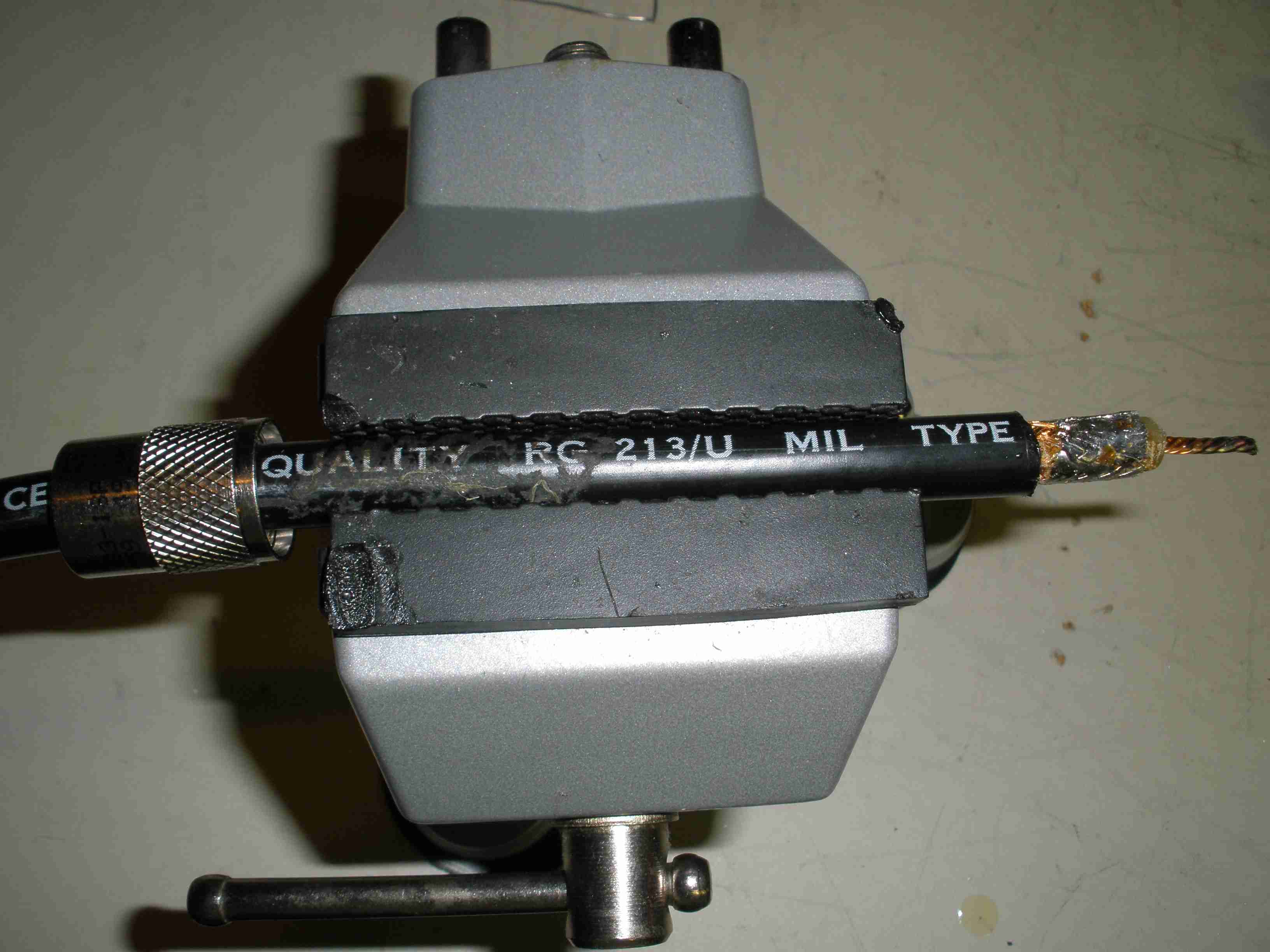
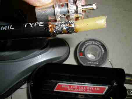 Now apply sparingly some solder flux to the braid. DO NOT DISTURB THE WEAVE OF THE BRAID.
You want it to fit easily into the connector. Tin it, working quickly on a small section.
DO NOT APPLY LARGE AMOUNTS OF SOLDER, or the coax will not fit into the connector.
Do not let the braid bulge up or it won't fit either.
Let cool, rotate it in the vise to expose a new quarter section. Work your way around til you are done.
If necessary, remove any excess solder. Also, if necessary, use a pair of slip joint pliers to persuade the braid to conform to the center insulator as close as possible.
Carefully remove any loose strands at the right hand side which could short the coax later.
Tin all the way up to the jacket. Why? As you screw on the connector can push the braid to the left.
This can bunch up and prevent the connector from screwing on. Worse yet, the braid might no longer be visible in the connector solder holes.
TIP: Persistent solder balls can be removed by filing with a modeler's file, but avoid damaging the braid.
Now apply sparingly some solder flux to the braid. DO NOT DISTURB THE WEAVE OF THE BRAID.
You want it to fit easily into the connector. Tin it, working quickly on a small section.
DO NOT APPLY LARGE AMOUNTS OF SOLDER, or the coax will not fit into the connector.
Do not let the braid bulge up or it won't fit either.
Let cool, rotate it in the vise to expose a new quarter section. Work your way around til you are done.
If necessary, remove any excess solder. Also, if necessary, use a pair of slip joint pliers to persuade the braid to conform to the center insulator as close as possible.
Carefully remove any loose strands at the right hand side which could short the coax later.
Tin all the way up to the jacket. Why? As you screw on the connector can push the braid to the left.
This can bunch up and prevent the connector from screwing on. Worse yet, the braid might no longer be visible in the connector solder holes.
TIP: Persistent solder balls can be removed by filing with a modeler's file, but avoid damaging the braid.
 Now you are ready to prepare the center conductor. Remove the insulator in the center conductor using the technique used on the jacket.
DO NOT cut all the way through the insulation, leaving a thin coating over the wire. Slightly bend the right hand end to finish breaking the insulator loose.
Do not disturb the weave of the braid.
Grasp the right hand end of the center conductor insulation with slip joint pliers, and rotate it while pulling, in a fashion that preserves the twist of the center conductor.
The goal is to leave a portion of center insulator which prevents the braid from shorting to the center pin when it is assembled.
Use flux sparingly and tin sparingly the center conductor. This prevents the center conductor from fraying as you screw on the connector, which can also cause shorts in the assembly.
Now you are ready to prepare the center conductor. Remove the insulator in the center conductor using the technique used on the jacket.
DO NOT cut all the way through the insulation, leaving a thin coating over the wire. Slightly bend the right hand end to finish breaking the insulator loose.
Do not disturb the weave of the braid.
Grasp the right hand end of the center conductor insulation with slip joint pliers, and rotate it while pulling, in a fashion that preserves the twist of the center conductor.
The goal is to leave a portion of center insulator which prevents the braid from shorting to the center pin when it is assembled.
Use flux sparingly and tin sparingly the center conductor. This prevents the center conductor from fraying as you screw on the connector, which can also cause shorts in the assembly.
 I show this as a separate step for a reason. Install the outer ferrule that screws on the exterior of the coax connector at this point.
It will wreck your day if you forget this step, because you will have to cut the connector off and start over, if you do not remember this important step!
I show this as a separate step for a reason. Install the outer ferrule that screws on the exterior of the coax connector at this point.
It will wreck your day if you forget this step, because you will have to cut the connector off and start over, if you do not remember this important step!
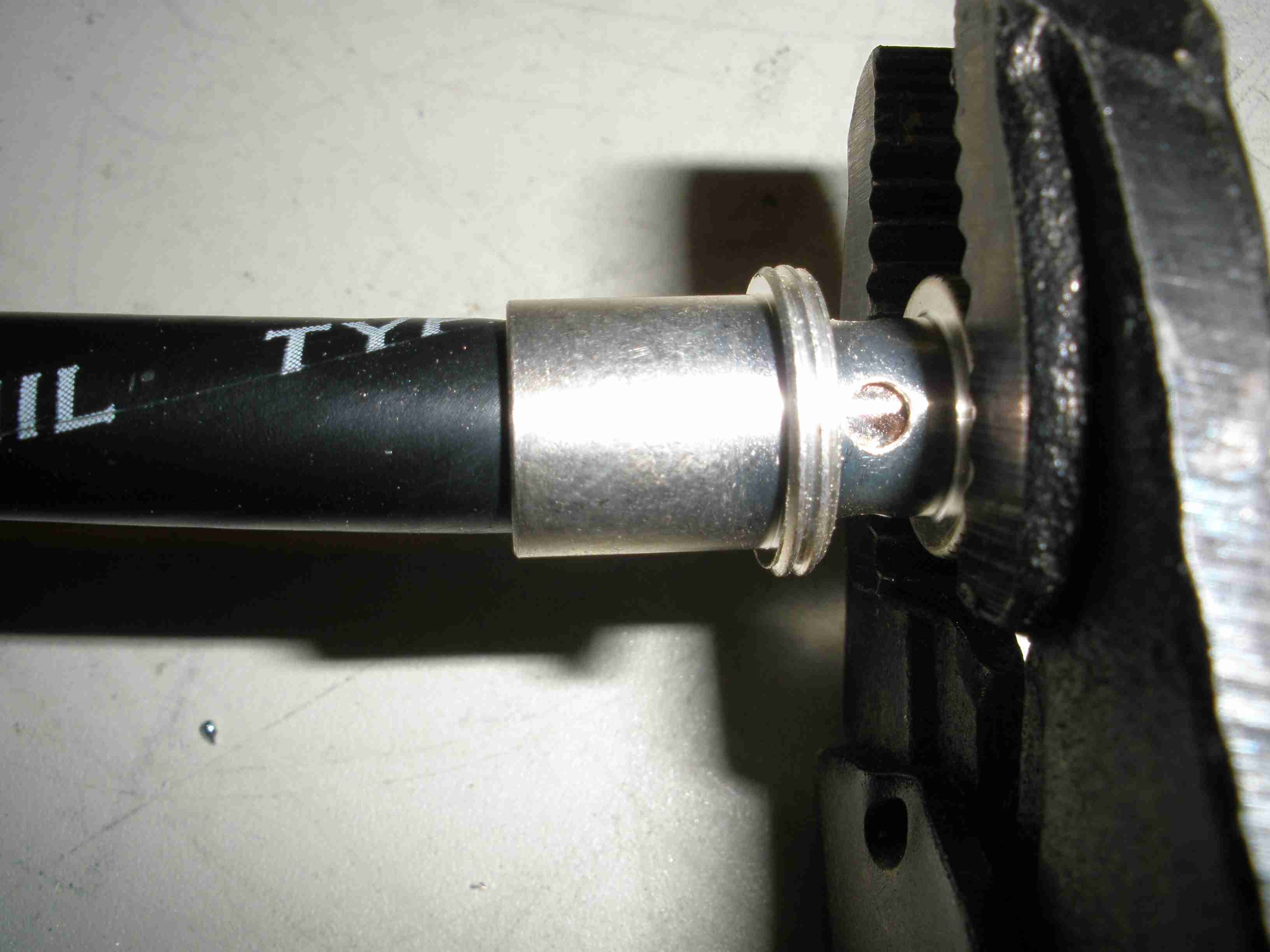
 Hold the cable in your left hand. Use a pair of vice grip pliers to hole the coax connector.
DO NOT OVERTIGHTEN. I usually apply the pliers loosely as shown, and turn the knob til it just holds the connector.
Rotate the connector clockwise as viewed from the pin end using the pliers. Lefty-loosie, Righty-tighty!
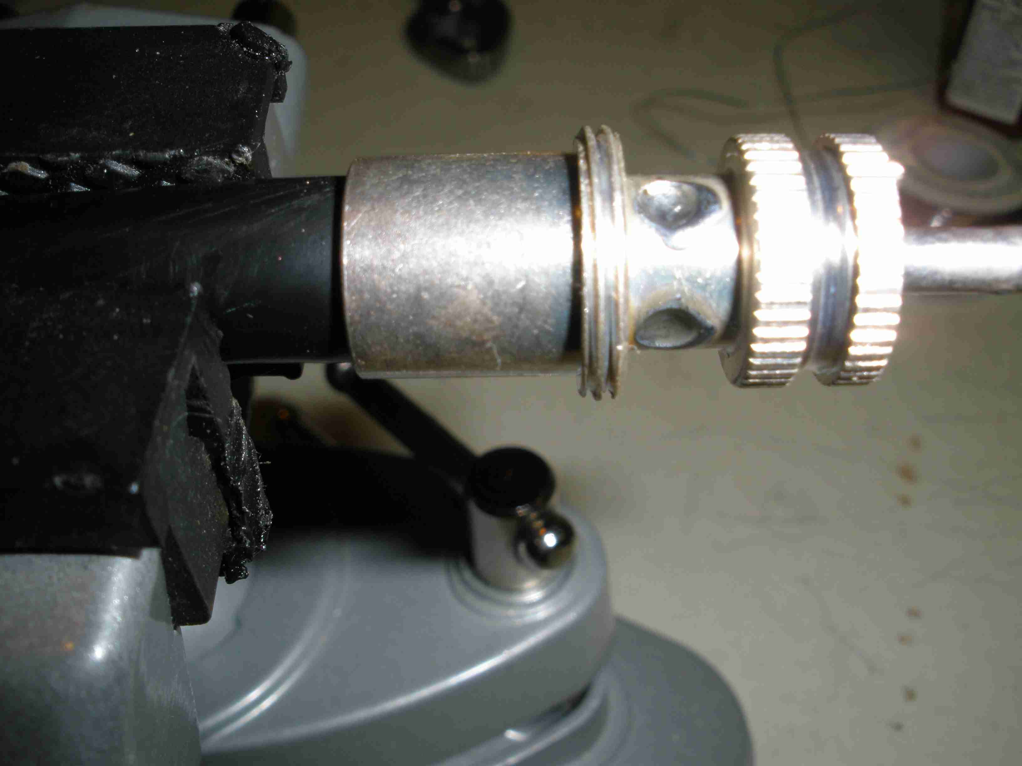
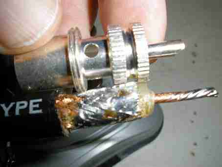
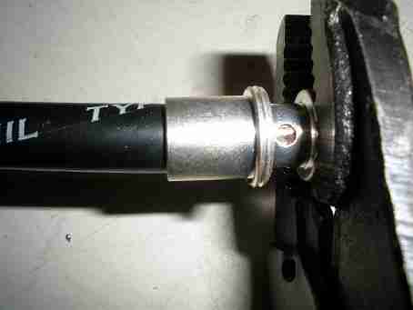
Eventually, the coax will screw into the connector. Stop when the braid shows in the connector holes and the coax is tightly held.
The goal is to have the tinned braid show in the connector hole as shown.
Hold the cable in your left hand. Use a pair of vice grip pliers to hole the coax connector.
DO NOT OVERTIGHTEN. I usually apply the pliers loosely as shown, and turn the knob til it just holds the connector.
Rotate the connector clockwise as viewed from the pin end using the pliers. Lefty-loosie, Righty-tighty!
Eventually, the coax will screw into the connector. Stop when the braid shows in the connector holes and the coax is tightly held.
The goal is to have the tinned braid show in the connector hole as shown.
 Before soldering, test the connector for shorts with an ohm meter. If it does not pass this test, dismantle it by unscrewing it and fix the problem.
Using the 325 watt solder gun, solder one of the holes in the ground side of the connector.
Get the job done quickly without overheating, and let it cool. Rotate the cable assembly in the vise, and solder each hole, allowing cooling between each step.
The goal is to have a concave meniscus in each solder hole, indicating good wetting of solder to the braid and connector. If your cable looks like this, it will give you good reliable service.
Before soldering, test the connector for shorts with an ohm meter. If it does not pass this test, dismantle it by unscrewing it and fix the problem.
Using the 325 watt solder gun, solder one of the holes in the ground side of the connector.
Get the job done quickly without overheating, and let it cool. Rotate the cable assembly in the vise, and solder each hole, allowing cooling between each step.
The goal is to have a concave meniscus in each solder hole, indicating good wetting of solder to the braid and connector. If your cable looks like this, it will give you good reliable service.
Allow the connector to cool enough that you can touch it comfortably. Then solder the center conductor; do not apply excessive heat or take too long.
This part will go quickly because there is not as much mass to heat up to get a good joint.
There will be excessive wire sticking out the right hand side. This was allowed during preparation to ensure the center conductor would go into the center pin without bending or fraying.
Remove all solder balls from the center pin. If the center pin is too thick, it can damage the female connector it is plugged into.
Make one last check with an ohm meter for shorts and continuity. Enjoy a reliable cable that will last you for years!
COMING ATTRACTIONS:
HOW TO INTALL COAX CONNECTORS ON RG-8/M OR RG-59 SMALLER DIAMETER COAX
A TRICK TO GETTING THE ADAPTER RIGHT, AND ENSURING A RELIABLE GROUND.
Ever wonder what the RG stands for in RG-8/U? Back in World War II, the military developed coaxial cable to replace quirky open wire feeders.
It stands for "Radio Guide". At VHF/UHF frequencies, plumbing style construction is referred to as "Wave Guide."
|