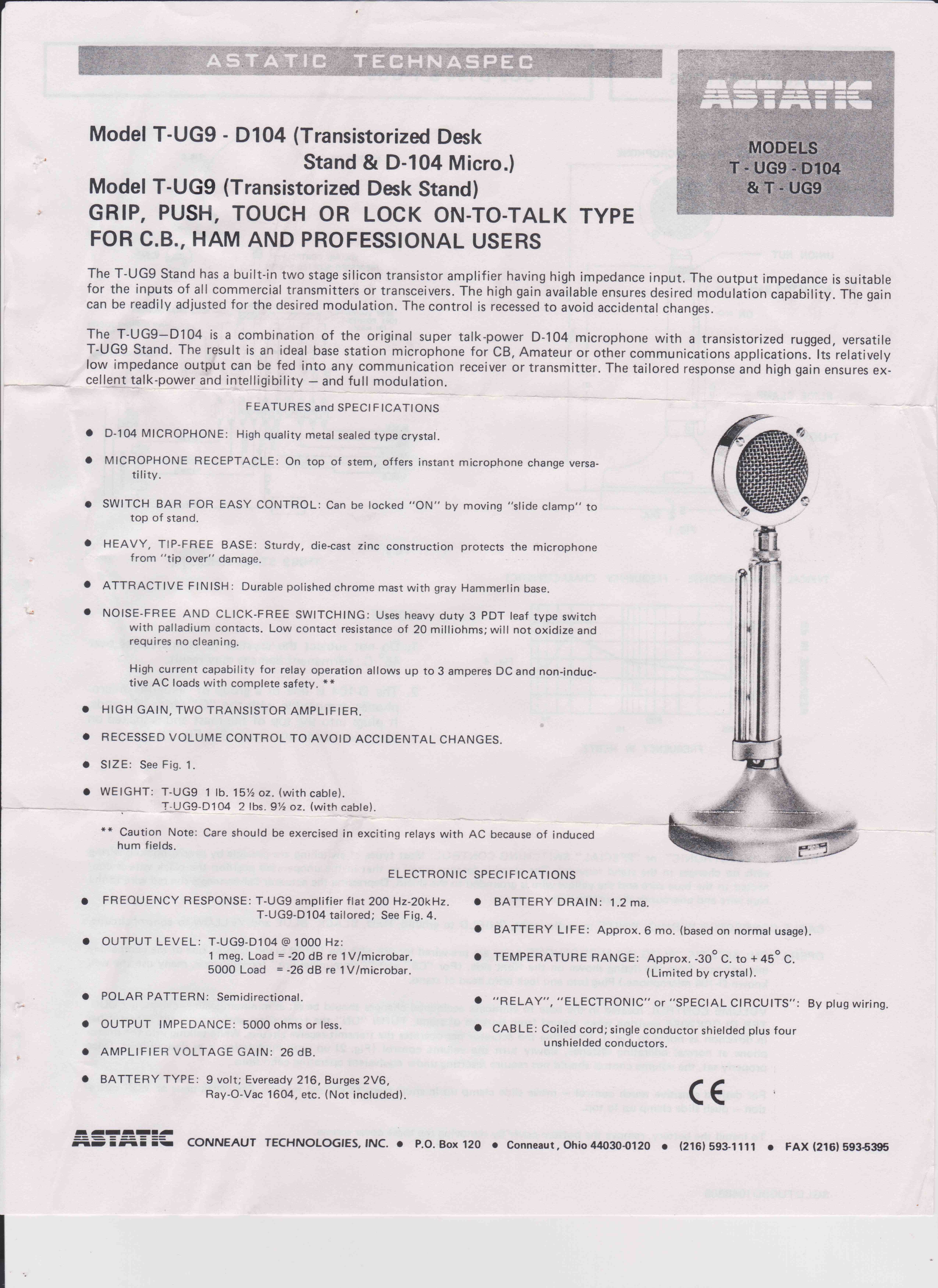
|
The K7DYY D104 Microphone Audio Processor Board is an asset to any transmitter. Originally designed as a quick and easy way to get the K7DYY Super Senior AM transmitters on the air, it can be used with any rig. It costs about $80 plus shipping. Buy it at: http://www.k7dyy.com/.
ASTATIC MIKE HEADS FOR THE D104 STAND
The K7DYY processor board also works with the other "bullet style" (DN & 10C) and Astatic 77 mike heads that plug into the "G" style D104 stand. The 77 head dates back as far as 1945 for an authentic vintage look. I have one of these with a bad element, and may fix it, just for its vintage look. It predates the iconic "Elvis Mike" the Shure 55, and is similar in looks.
http://antiqueoutings.com/astatic-77-microphone/
Here is a sharp looking chrome T3. Introduced around 1960, it was a favorite with harmonica players.
https://vintagemike.wordpress.com/2011/12/01/astatic-model-t3/
REPLACING BAD D104 ELEMENTS WITH MODERN MIKE ELEMENTS
The K7DYY D104 mike processor board was designed to use a standard D104 Lollypop head on a G stand with a K7DYY Super Senior transmitter. I have also successfully used that configuration to drive my Viking II and DX-40. Use with anything other than an original crystal element in a D104 head has been disappointing. I recommend that you only use the K7DYY D104 Mike processor board as originally intended.
Please do not deface a working original lollypop D104 head. Try to find one of the other styles for any element mods. The combination of an authentic D104 original and the K7DYY processor will give you a lot of punch and great sounding audio, without the complication and expense of a rack full of gear.
There is an electret condenser mike element by W2IHY. The K7DYY processor has all you need to use an electret element, such as a bias supply. You can buy that mike element for installation in a D104 head here:
http://w2eny.com/D104Replacement/
Heil has mike elements too. They just released the 5.1 retrofit kit with transformer. Buy it here:
https://www.dxengineering.com/parts/hls-hc51retrokit.
Read reviews at:
http://www.eham.net/reviews/detail/5530?ehamsid=197je2aqgbimfft6kitlt2n9b3
The reviews give it high marks. My thinking is that the electret mike element sounded too bassy without a VERY small coupling capacitor to treat the boominess. VERY AGGRESSIVE EQ IS NEEDED separate from the K7DYY mike processor. The Heil design has a built in presence rise for better articulation on both AM and SSB. The original HC-5 element was rectangular, and possibly had different characteristics from the new HC-5.1 that is currently available. I tried it with the K7DYY D104 mike processor board, and found it sounded muffled. IT WOULD REQUIRE AGGRESSIVE EQ TO CORRECT THAT PROBLEM. I still prefer the original D-104 cartridge, due to not as much presence rise in the Heil unit. A circuit of your design, to provide that presence rise might be added in the D-104 base.
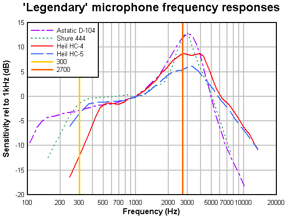
Here is a comparison of the original D-104, Shure 444, and Heil HC-4 and 5 elements from M0MTJ and VK1OD. There is a lot of other useful information there.
The Kobitone crystal elements Mouser used to sell got good reports as a direct sub for the D104 crystal element. They are no longer available.
LET ME STATE UNEQUIVOCALLY: THE K7DYY D104 MIKE PROCESSOR WAS DESIGNED TO USE A GENUINE D104. USE IN ANY OTHER WAY DID NOT WORK FOR ME. FEEL FREE TO EXPERIMENT ON YOUR OWN. THE FREQUENCY RESPONSE GRAPHS OF THE VARIOUS MIKES ON THIS WEB SITE DEMONSTRATE THAT AGGRESSIVE EQUALIZATION WOULD BE REQUIRED TO MAKE ANY OTHER ELEMENT WORK. THAT EQ IS NOT PROVIDED IN THE K7DYY UNIT, AND I DO NOT HAVE A CIRCUIT TO SHARE TO FIX THAT PROBLEM. I USE ONLY GENUINE D104 CRYSTAL ELEMENTS AT MY STATION.
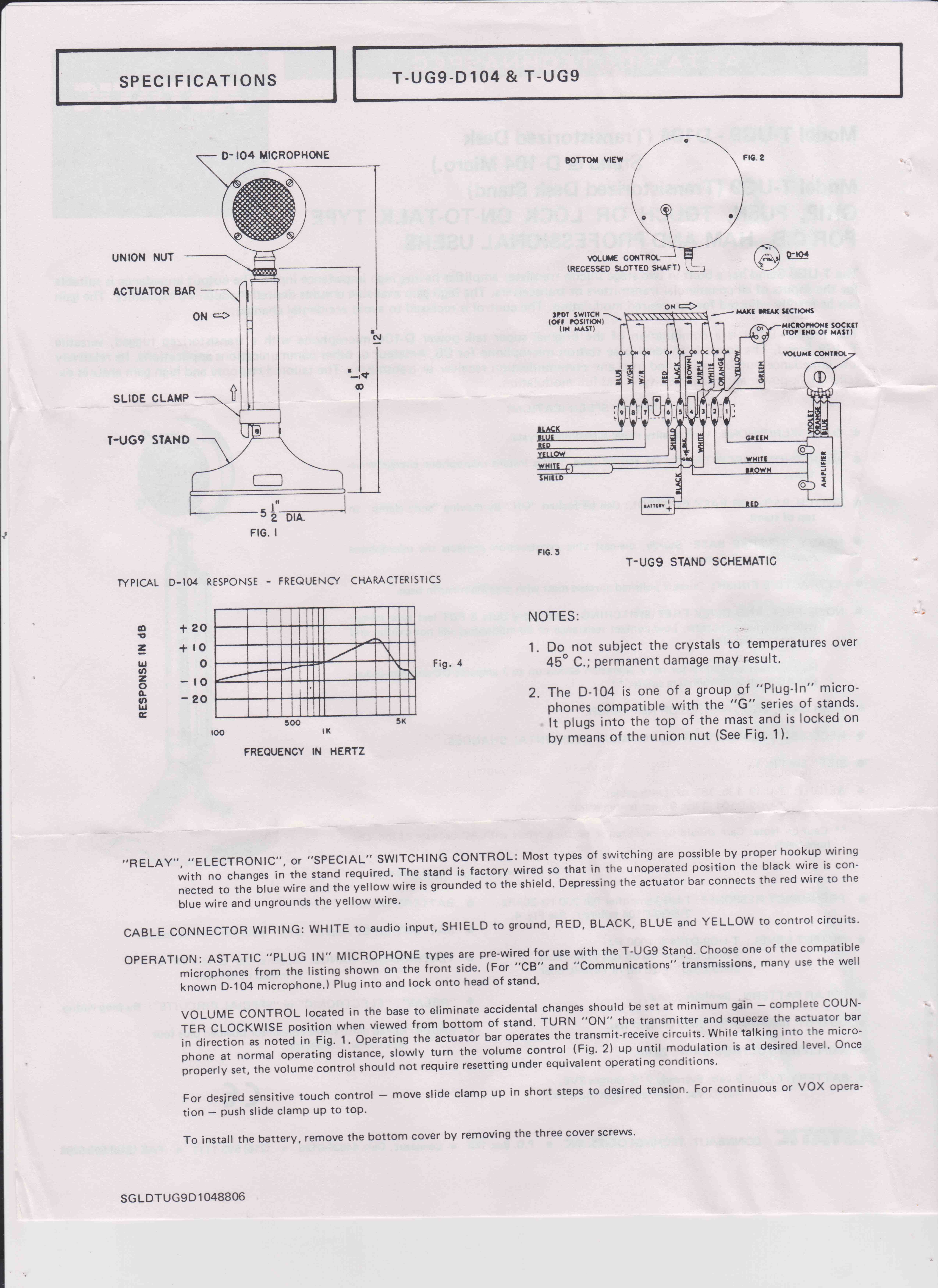
WIRING DIAGRAM OF THE D-104 AND G STAND FOR REFERENCE
There are many variations of the G stand out there, but this is the most common. It includes the battery connector and a level control, so it is the most desirable for this modification. Click on either image to enlarge it. Click again to get a really magnified view. The K7DYY board replaces the original preamp from Astatic. Note that the black version with the horizontal actuator on the base rather than the side will NOT work because the board will not fit.
INSTALLING AND USING THE K7DYY PROCESSOR BOARD
Let's get back to the K7DYY processor board. This board contains three essential features to get good performance from the D104 classic crystal mike element (sometimes referred to as a "lollypop" mike).
The first feature is a high impedance load to get the full audio spectrum response from the D104 crystal element. This consists of a 6.8MΩ load and a FET to drive the next item in the audio chain.
The second feature is a 2167 Integrated Circuit which serves as a hard limiter (to prevent overmodulation) as well as a compressor function to provide more audio punch. There is also a downward expander or noise gate. The improved Mark 2 boards have a jumper to turn off the noise gate function, which most AM operators prefer not to use. You may want to try the downward expander if you use this with a vintage SSB rig. I use the older boards which did not have this jumper on my vintage SSB gear, because it reduces background noise (like fans on my "active antenna couplers") between phrases.
The third feature is a low impedance emitter follower to drive the LINE LEVEL input of the K7DYY Super Senior Transmitter to full 1500 Watt peak output. This full legal limit transmitter requires a low impedance source provided by the transistor. The transistor output stage is unity gain. Emitter followers provide no amplification but have a low impedance output and a high impedance input. This prevents switching noise inside the K7DYY transmitter box from getting into the audio. I also used this on my E. F. Johnson Valiant to cure nasty RF in the audio on 10 meters. The low impedance drive from the K7DYY Audio Processor Board attenuated any RF pickup and AC hum, owing to its low output impedance.
For modern ICOM rigs DO NOT FORGET TO USE A DC BLOCKING CAPACITOR IN THE OUTPUT LEAD. See your Icom manual and the information on the Heil sound page for details. The output control pot will provide a DC path to ground unless you take care of this detai.
There are questions about which Astatic stands can be used for the K7DYY Audio Processor board. See the photos and text at the end of the article for mechanical fit considerations.
For operation with the K7DYY Super Senior Transmitter you can use ANY of the stands, even the ones without an Astatic amplifier in the base. This is true because the K7DYY Super Senior Transmitter provides all DC required to operate the K7DYY Audio Processor Board. The original or the W2ENY mike element connects directly to the Audio Processor Board input as shown in the schematics furnished with the K7DYY Audio Processor Board. The output goes to the mike connector pins shown in the K7DYY documentation. The Normally Open switch contacts in the grip to talk stand go to the Push to Talk Line in the K7DYY Super Senior Transmitter as shown in the furnished documentation. Of course, a D104 that has an Astatic amplifier will work fine also.
For operation with other transmitters such as the E. F. Johnson Valiant, it is more convenient to use a TUG8 or TUG9 stand that has an Astatic amplifier. The battery clip and output control resistor are left in the Astatic stand. The Astatic amplifier in the base is removed; it never provided a high impedance load for the element, which is why the Astatic amplifier sounded very high pitched and had no lows. The Astatic amplified D104 was popular as a "power mike" to overdrive the mike input of a CB radio to make a signal louder and splatter over more channels. The battery holder can be used with the new K7DYY Audio Processor and one set of contacts to turn the power on and off to the K7DYY Audio Processor Board. Another separate set of contacts can be used to close the PTT line in the K7DYY Super Senior Transmitter. There will be spare contacts left over which can be insulated with some shrink tube. NOTE: be sure to disconnect any switch contacts that may have been used to short the mike element. These are no longer necessary. You can use the D104 existing gain control adjustment between the D104 processor and the K7DYY or any other rig you connect it to. If you have both the K7DYY 160/80 and the 80/40, you will need this feature because the two rigs are not exactly the same level setting.
You may ask "Doesn't switching the power on and off make a transient pulse?" I have tested this on the air and with a scope attached directly to the audio output. There is a minimal pulse caused by switching the power to the K7DYY Audio Processor, but the peak limiter helps prevent huge spikes. Apparently the 2167 Integrated Circuit takes care of it. That makes sense, because the chip is meant to drive Analog to Digital Converters without overloading them.
The original output control in the D104 base can be used to adjust the level going to a classic transmitter or the K7DYY Super Senior Transmitter. Wire the K7DYY first to the outer terminals of the existing 1K pot in the D104 base. Turn the K7DYY Audio Processor Board output pot R5 all the way up, if using a "line" output for the K7DYY transmitter. Turn the pot on the board down to 10% and use the D104 base pot for fine adjustments if driving a vintage rig with a mike low level input. Take the output from the wiper of the 1K pot and the ground terminal. With an RF monitor scope, adjust the existing 1K pot through the hole in the base while saying the word "Five" as if it was "FAAAIIIIEEEEEVE" at a normal distance and level. Bring the pot up in level til the scope just kisses the base line for 0% modulation and check the upward peaks do not flat top. If the waveshape of the crystal mike element and your voice are not symmetrical, you can flip the wires to the cartridge to avoid the 0% and get higher upward peaks. (The phase rotator in the Mark 2 model automaticallly corrects this problem.) Then scream loud and make sure it does not overmodulate when it hits the limiter in the audio processor. NOTE: The K7DYY Audio Processor has a symettrical peak limiter in it that will keep your signal clean. The distortion resulting from processing is very low, less than 0.2%.
The symettrical limiting of the 2167 IC does not allow the practice of higher upward peaks of modulation percentage. This is "old school thinking" relating to tube transmitters. It was a method of getting a little more punch from a transmitter, if you had spare power in the audio system. The K7DYY Super Senior transmitter has two limits that must not be exceeded. You must not run a output carrier power in excess of 375 Watts. The rigs drift upward in carrier output level as they warm up; so set it at 300 Watts cold, and observe it while transmitting tests into a dummy load to make sure you do not exceed this level warm. Some people back them down to 200 Watts carrier. The upward modulation peaks must not exceed 1500 Watts. That is 4 times 375. So there is no advantage in having non symettrical modulation from the standpoint of the specs. I suppose you could run 200 to 250 Watts carrier, and have 1500 Watts upward peaks, as long as the downward audio drive does not hit the baseline (0% modulation). You would have to use an external audio chain with those capabilities though. The D104 processor does not work that way. Another consideration is that most vintage receivers do not tolerate much more than 120% upward peaks without distortion. Synchronous detectors will work fine that way, but not everybody is using them.
The audio frequency response of the 2167 Integrated Circuit is flat well beyond the audio spectrum. The Mark 2 added some roll off to reduce this excess HF response beyond the audio spectrum. If you are using an old K7DYY audio processor (not the Mark 2) you may get some protection trips on overmodulation from this energy above 10 KHz. This means that any frequency equalization has to be done AFTER the K7DYY Audio Processor Board. Keep in mind that you have to do more extensive testing of overmodulation at various frequencies that you have accented. One way to avoid problems is to set all controls on the eq at the same level (flat), maybe all at +3 dB. Set the modulation level correctly as noted above. Then REDUCE any unwanted frequencies. DO NOT BOOST anything from the initial settings. Overmodulation will not occur if you do it this way.
Note that if you equalize before the 2167 IC, the compressor undoes the equalization because its job is to make signals more level. In fact, it may increase unwanted frequencies louder in comparison to the ones you want - exactly the opposite of what you intended! This is only a simplified explanation. There are much more extensive discussions on the internet by audio authorities. Research it and come up with something that satisfies YOUR taste. If you ask more than one person on the air about your signal, you will get different opinions. Set your goal after you study the problem. If you want a broadcast sound, it will be totally different from a QRM busting punchy sound.
In any event, you have to decide for yourself how you want to sound. The occupied bandwidth is also an issue. Any "audio chain" rack mounted equipment you may have has a lot of adjustments to play with. This simple board, not much larger than a postage stamp, packs a lot of performance into the base of the D104 mike. It is possible to add a low pass filter on the "back end" of the K7DYY D104 mike processor board to tighten up the occupied band width. I may experiment with that later, and post the results here. At the end of the article, I show the total response curves for both an electret condenser mike and the classic D104 crystal element when used with a K7DYY D104 processor board. Keep in mind that the upper frequency response for the 160/80 is about 10 KHz and the 80/40 is about 8 KHz. This can be a factor if you wish to operate with a carrier at 7295, or 3705 (if you are an Advanced class). The sidebands in that case would be out of band or outside you operating privileges.
One final comment needs to be made about the original version D104 mike processor downward expander or noise gate in the K7DYY Audio Processor as a feature of the 2167 IC. You can play a bit with the expansion ratio by changing the value of R2 on the board. It is set from K7DYY at slightly over 5:1 ratio. Making the compression ratio lower by reducing R2 to as low as zero for 1:1 reduces the perceived effect of the downward expander. Adjustment of either the compression ratio or the downward expander does NOT effect the limiter rotation point (modulation limiter). The K7DYY Audio Processor is factory set for minimum effect with R3 at 4.7K.
I found that I was able to disable the downward expander with a 10K resistor parallelled with R2 and removing R3. Of course, the compressor function is now almost nonexistent, but the limiter function to protect the K7DYY transmitter from over modulation still works. Note that these comments do NOT apply to the newer Mark 2 version.
ANY AM transmitter MUST employ a modulation "hard" limiter (clipper) to avoid transmitter damage and splatter. These D104 boards provide that protection when properly adjusted. I have spoken with hams using, for instance, a Behringer 528E or something like it; it has compression, but does NOT furnish the hard limiter function necessary to protect the K7DYY rigs. They get a lot of nuisance protection trips, and may eventually damage the K7DYY Super Senior transmitters if abused with excessive modulation drive.
There is a chip manufacturer evaluation board available, but it does not have the FET input buffer or the emitter follower buffer. It does have an assortment of resistor values already mounted to the board to obviate the need for you to solder surface mount parts to make adjustments. Also, the IC manufacturer's board is not designed to fit in a D104 base conveniently. If you decide you want to tinker with the adjustments, here are the 2167 IC spec sheets and the evaluation board:
 |
|
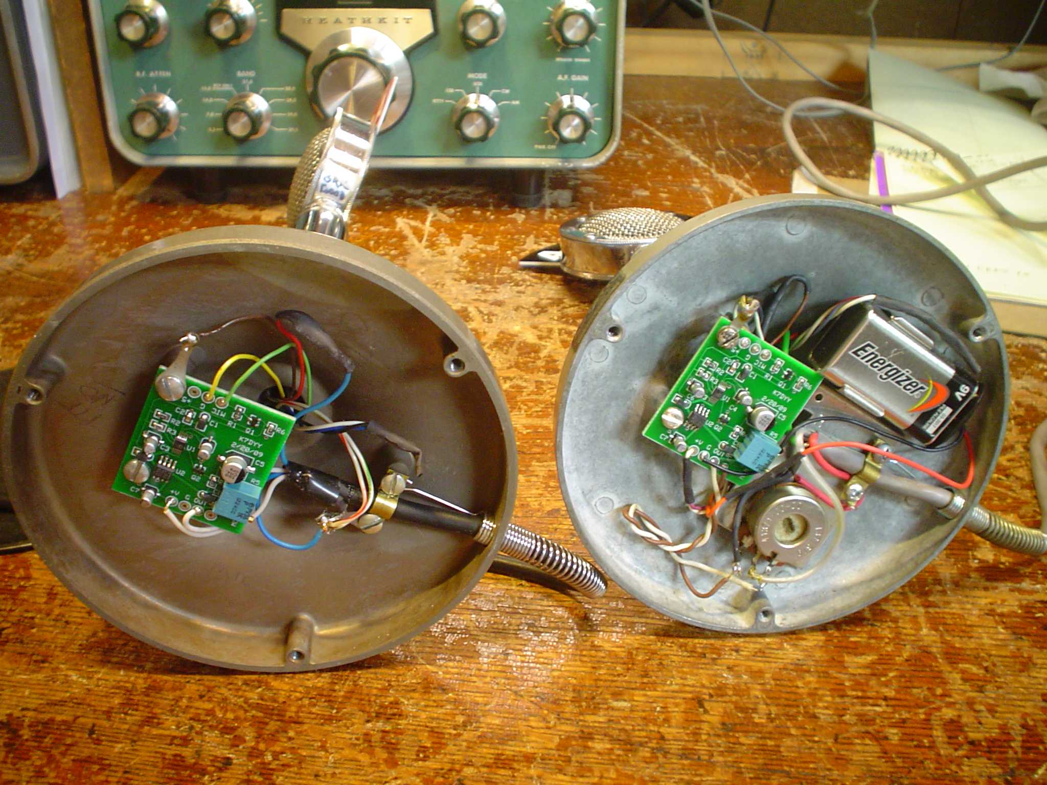
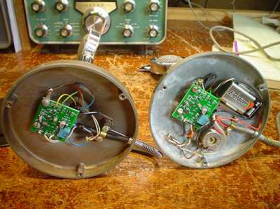
You can see the two styles of D104 mike stands with the K7DYY Audio Processor board installed. The one on the left is an older stand without the Astatic amplifier for my K7DYY Super Senior Transmitter. There is plenty of clearance to the bottom cover with this style. The one on the right is an Astatic stand that originally had an Astatic amplifier, which I use for my Vintage gear, because it already had a battery holder. Clearance can be tight with this style. Early Mark 2 boards need the Noise Gate pins bent over to parallel with the PC board to avoid shorting to the cover. This was corrected in the second production run with shorter pins. You can also put a thin piece of insulating paper on the bottom cover. |
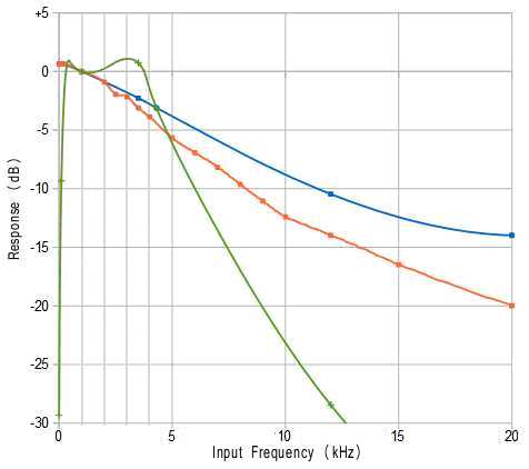
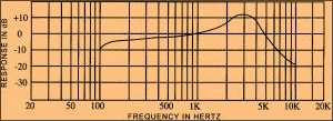
| The frequency response of a D104 operating into a proper load is as shown: |
|
 |
 |
|
Note that you do not have to go much above 5 MΩ load to experience frequency response from the D104 that is good enough for most amateur audio systems. K7DYY uses 6.8 Megohms. Refer to Electric Radio #306, November 2014 for a complete discussion and tube preamplifier and push pull modulator grid driver system which correctly presents a 20 MΩ load to the D104. The article is written by K4KYV. |
|
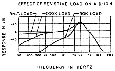
THIS GRAPH DEMONSTRATES THAT ONLY A TRUE D104 CRYSTAL ELEMENT DELIVERS ACCEPTABLE RESPONSE WITHOUT AGGRESSIVE EQ. It is provided as guidance, if you want to experiment with other elements and EQ circuits. This frequency response curve is measured data on the production run D104 Mark 2 processor board that I have bought. The 100K compression control resistor (R17) was paralleled with a 22K resistor to reduce the amount of background noise and provide less aggressive compression. This noise is usually the fans some seem to complain about; they are really quiet, but the processor gain is high. These tests would have been difficult to do, run at the stock gain, but the curves would be the same. The ORANGE curve is with levels BELOW the compression threshold, and demonstrate the effect of the first RC network between the phase rotator circuits and the 2167 IC input. This saves the 2167 chip from pumping the AGC on energy that is not in the audio spectrum. The BLUE curve is data for normal use above the compression threshold, for normal speech. The roll off is primarily controlled by the RC network between the 2167 IC output and the emitter follower output transistor base. This BLUE curve is the response you would obtain with a flat frequency response device such as an electret condenser mike, which the K7DYY data sheet explains how to connect. With an electret condenser mike element, the transmitter occupied bandwidth is pretty broad (twice the audio bandwidth, due to both sidebands) and great care would have to be exercised when operating anywhere band edges. In comparison, the classic D104 crystal mike element is far from flat, as can be seen by the response curves for it shown above. If you combine the typical response curve for a D104 crystal element with the K7DYY D104 Mark 2 processor board, the resulting frequency response curve is the GREEN one. This provides good presence rise at the proper frequency, and results in a bandwidth that is more neighborly to adjacent frequencies.
|
To finish off the project with a flourish, add a mike flag on top bearing your call letters from:
http://www.hamcrazy.com/.
|