| Johnson 122 VFO with Grid Block Keying Mods with WARC bands | |||||||||||||||||||||||||||||||||||||||||||||||||||||||||||||||||||||||||||||||||||||||||||||||||||||||||||||||||||||||||||||||||||||||||||||||||||||||||||||||||||||||||||||||||||||||||||||||||||||||||||||||||||||||||||||||||||||||||||||||||||||||||
|---|---|---|---|---|---|---|---|---|---|---|---|---|---|---|---|---|---|---|---|---|---|---|---|---|---|---|---|---|---|---|---|---|---|---|---|---|---|---|---|---|---|---|---|---|---|---|---|---|---|---|---|---|---|---|---|---|---|---|---|---|---|---|---|---|---|---|---|---|---|---|---|---|---|---|---|---|---|---|---|---|---|---|---|---|---|---|---|---|---|---|---|---|---|---|---|---|---|---|---|---|---|---|---|---|---|---|---|---|---|---|---|---|---|---|---|---|---|---|---|---|---|---|---|---|---|---|---|---|---|---|---|---|---|---|---|---|---|---|---|---|---|---|---|---|---|---|---|---|---|---|---|---|---|---|---|---|---|---|---|---|---|---|---|---|---|---|---|---|---|---|---|---|---|---|---|---|---|---|---|---|---|---|---|---|---|---|---|---|---|---|---|---|---|---|---|---|---|---|---|---|---|---|---|---|---|---|---|---|---|---|---|---|---|---|---|---|---|---|---|---|---|---|---|---|---|---|---|---|---|---|---|---|---|---|---|---|---|---|---|---|---|---|---|---|---|---|---|---|---|
|
The Johnson Viking 122 VFO is the best basic VFO ever made: stable, accurate calibration, high bandspread tuning, common replacement parts. The contemporary competition for the Johnson 122 VFO fell short by comparison. The Heathkit VF-1 by comparison is cheaply made, with ceramic calibration trimmers instead of precision air variable capacitors. Worse yet, the plastic dial calibration is so inaccurate that you will never get closer than 5 KC dial tracking; you can get the Johnson 122 to track almost 1 KC. The dial drive on the VF-1 is located in the center, resulting in difficulty of zero beating or tuning to the correct transmit frequency. Often the plastic dial is chewed up beyond use or cracked badly. In a pinch, you can cob a replacement out of an old CD. The Johnson 122 VFO drives from the EDGE of the METAL tuning dial for more precise tuning. Both were in the same price range as kits. Further, the Johnson 122 VFO lends itself well to a factory original design grid block keying modification. The VF-1 has some non factory mods out there on the web. The later Heath HG-10 does not cure the frequency stability problem, though it attempts to address the grid block keying issue, but at much higher cost. The Eico 722 is pretty good. The Hallicrafters HA-5 is superior for drift, but again at even higher cost and circuit complexity than the HG-10. The Hallicrafters HA-5, which uses a 5 MC oscillator heterodyned with crystals to get a 3.5 MC and 7 MC output is a rare find, but worth picking up if it is priced right. There are grid block keying mods for the HA-5. The HA-5 does not have 160 meters, and the Johnson 122 does, so that is the logical choice for the Johnson Viking 2 transmitter, if you plan to use it on 160 meters. If you plan to use the Johnson Viking 122 VFO with a transmitter other than the Johnson Viking II, such as the Adventurer or Challenger, I strongly recommend you power the 122 from a small separate power supply. Even when using the 122 VFO with the Viking II, a small power supply will allow you to warm it up without running the Viking II. On 15 or 10 meters, you may encounter chirp with the 122 and Viking II. You will encounter chirp due to the power supply instability of those more modest E. F. Johnson rigs. This method also reduces stress on the transformers in those small transmitters. This recommendation applies also to power either the VF-1 or the Johnson 122 VFO separately when using it with the Heathkit AT-1, DX-20, DX-35, and DX-40. To improve keying characteristics of the Johnson 122 VFO with the Viking II transmitter, use the E. F. Johnson approved modifications included at the end of the complete manual download available here: JohnsonVFOkeyingMod.pdf. If you only operate AM, you may not need to do the grid block keying mod. Downside: the OSC and BUF meter tuning have subtle swings now, but the receiver S meter can be used to peak the OSC and BUF tuning, until the normal GRID reading is sufficient to complete the tuneup. This is evident on 160, 60, and 30 meters, but all other bands are unambiguous. This mod keys the Pierce crystal oscillator very soft. The VFO keys perfectly. Note that a cathode keyed VFO will not work with a grid block keyed Viking II. Photos and description of a complete refurbishment project are now complete, and are included below. I used the E F Johson factory grid block keying modification, and the rise and fall times of the transmitted waveform are as good as any modern transceiver.
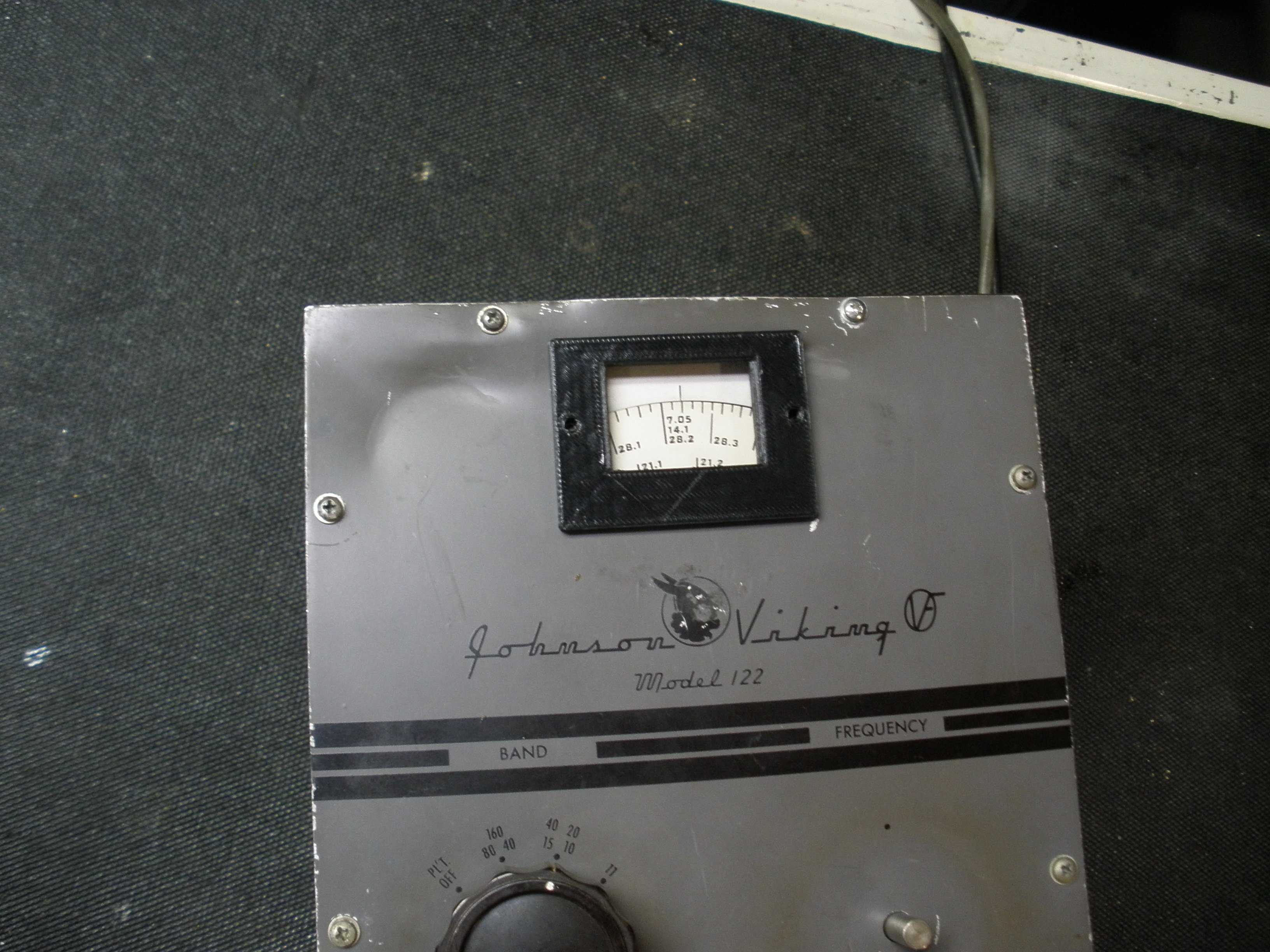
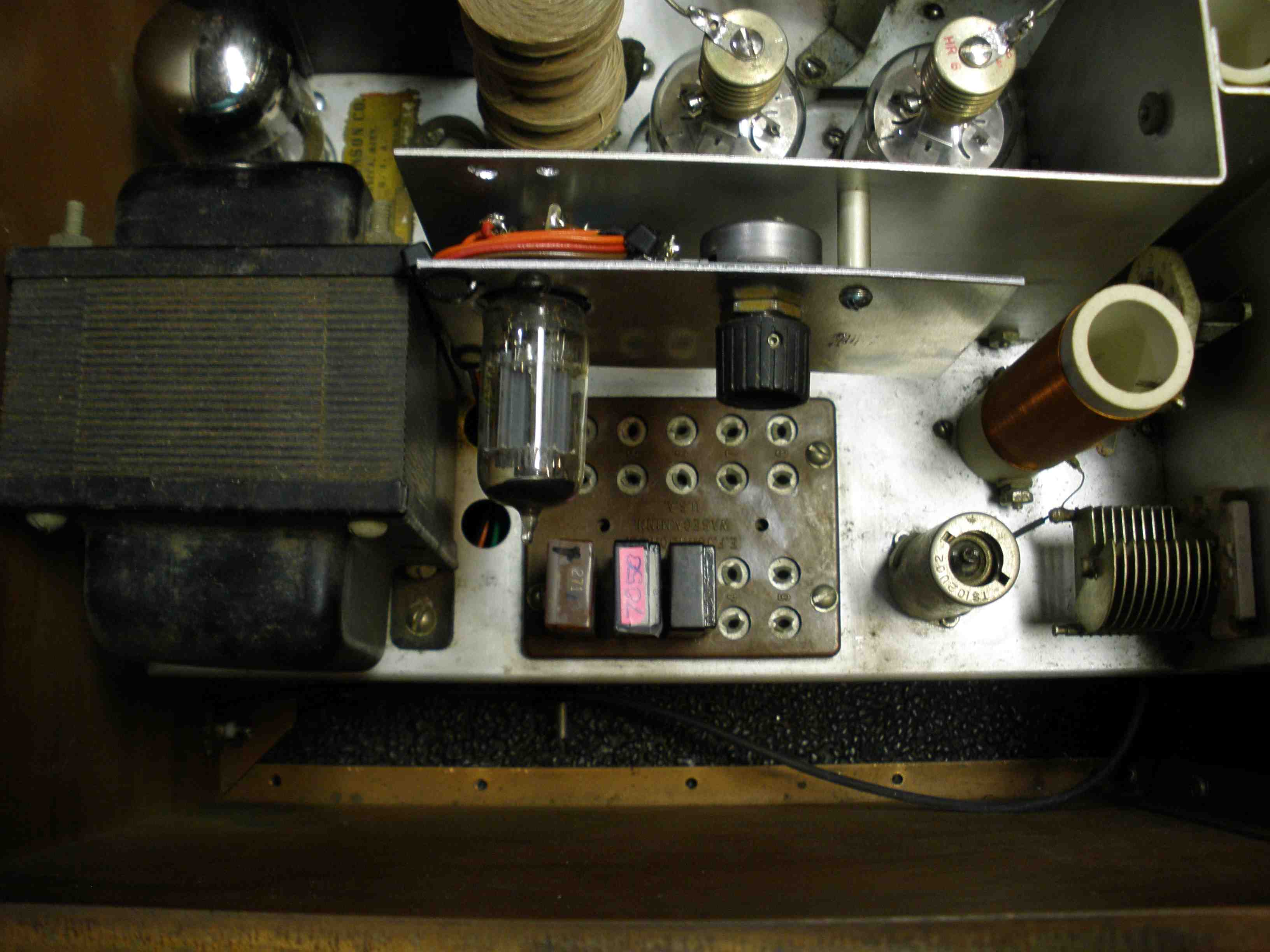
Before connecting a VFO to the Viking II, double check the wiring to the plugs. If the filament line is shorted, it can damage the wiring harness and RF choke at the socket. Bad soldering and sloppy wiring can leave threads of wire that can also cause problems. Correct all this before proceeding. Also shorts in the B+ wiring are catastrophic. A grid block keying item is not compatible with a cathode keyed item, so check for this modification to match the transmitter and VFO. Check the threads on the VFO connector in the back of the Viking II. Often they are stripped. I don't know why. You can sometimes clean them up with a scrap PL259 connector used as a die. DON'T force the VFO cable on there, or you will have two things to fix. If this doesn't work, you will have to replace the SO239 VFO RF INPUT socket. That is a project, but careful disassembly will preserve the needed parts to do the repair. Good news: If your 250-122 VFO front panel is damaged, you can buy a new one that matches exactly at: The Johnson knobs are still available used at various sources. Some cabinet parts are hard to come by. One of the VFOs I planned to work on was damaged in shipment, and the rectangular bezel around the frequency dial was damaged. I can straighten the front panel by placing it between two pieces of wood and tapping with a hammer. The internals of this VFO are OK, and the seller let it go dirt cheap due to the damage. These Johnson 122 VFOs are superior to the Heathkit VF-1, and well worth the work to refurbish. A friend made me a replacement bezel, using a 3D printer. Looks pretty good, doesn't it? 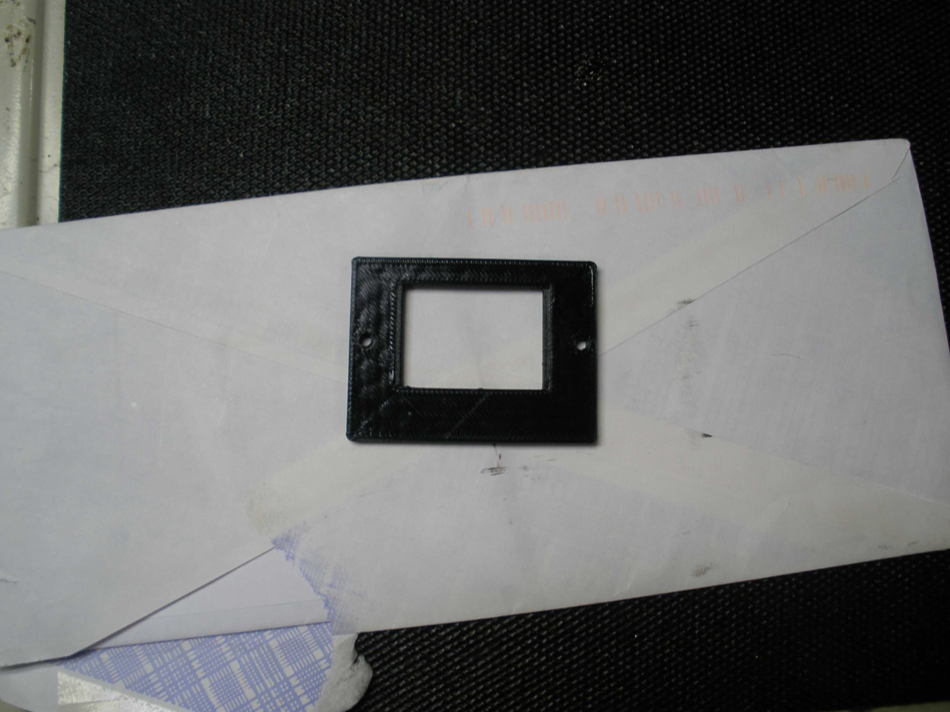
(click to enlarge) The 122 VFO is the most stable simple single tube VFO of its era. The VF-1 was a cheap unstable knockoff with inferior parts and mechanical design, but it can be adapted for grid block keying using these mods. The DX-100 used the VF-1 design, with an even longer switch shaft resulting in random frequency jumps of about 1 KC, in addition to the drift. An external VFO lowers drift. The stock Viking I and II used cathode keying on CW. When I was a teenager, I lived a few blocks from 4 active hams, and never got a complaint about my Viking II key clicks. One of the hams had a DX-100 (1955, upgraded 1957 to DX-100B) with clicks that caused problems for all of us, until I installed the Heathkit factory grid block keying modification in his rig. It caused "backwave" because the VFO was on whenever the plate switch was on, due to leakage through to the antenna, making break in operation impossible and causing strange signal reports. The EFJ grid block keying mod does not have this flaw, and it allows full breakin CW with the Viking II. There are only few reports of Viking II key clicks in online reviews; but looking at the cathode keyed waveforms, the rise and fall times are pretty steep. The ARRL Volunteer Monitors are currently enforcing key clicks. I intend to use the Viking II often on CW and the WARC bands. I even installed an AUDIO pot with a switch to turn off the 807 filaments when on CW for extended times. The Viking II grid block keying modification is nearly identical to that used in the Valiant (1956 - 1965) and Ranger II (1961 - 1965). I used a flat plate of sheet metal mounted to the vertical shield between the crystal sockets and the 6146 finals, duplicating the original Johnson kit. Note that V6 changes from a 6AU6 to a 6BA6 remote cutoff pentode. Increase C205 for longer rise and fall times. I tried a variety of ineffective or complicated solid state keying modifications. I finally used the EFJ keying circuit which worked great in the Valiant and was publicly documented. Below are links to the only correct schematic for the Johnson 250-122 VFO. It includes R55 (22 ohms) directly at the grid of the 6AU6 oscillator tube to stop VHF oscillation above 80 meters. I only use NONINDUCTIVE carbon or OX or OY type 150 ohms for R55. It also includes the complete text and schematics for the grid block keying modification. Don't forget to replace R51 (Chernobyl resistor) with a 5 watt unit. http://bama.edebris.com/manuals/johnson/vfo122/http://bama.edebris.com/download/johnson/keyermod/keyermod.pdf Another important link gives information about the meter wiring and grid block keying mod. Even though this is found in the Viking I directory, it applies to the Viking II as well. Be CERTAIN you follow the grid block keying installation directions, especially those related to the meter wiring. If done incorrectly, improper operation or meter damage may result. I strongly recommend you install parallel 1N4007 diodes pointing in opposite directions across the meter terminals. This prevents meter overload, and will not upset the meter calibration.
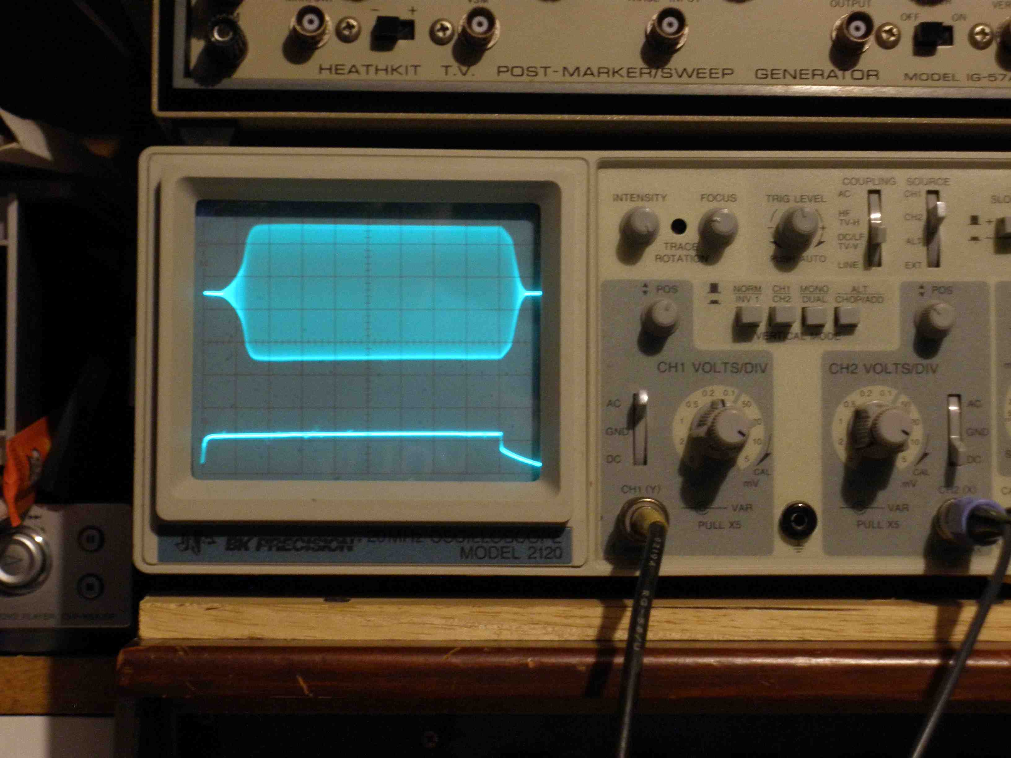
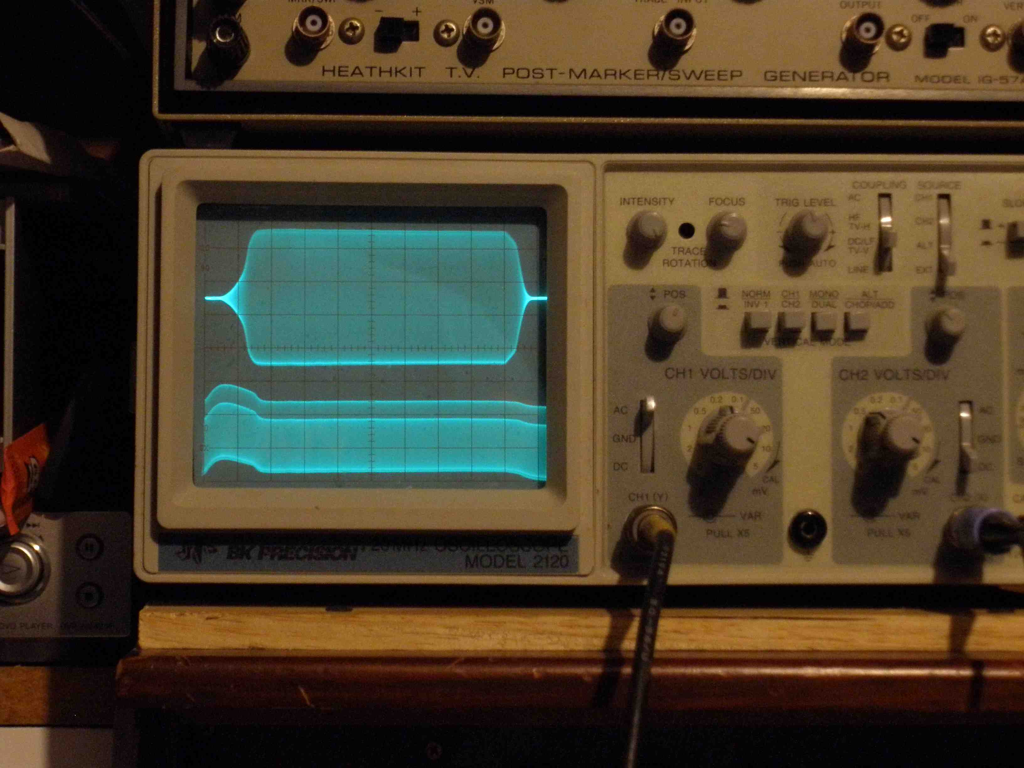
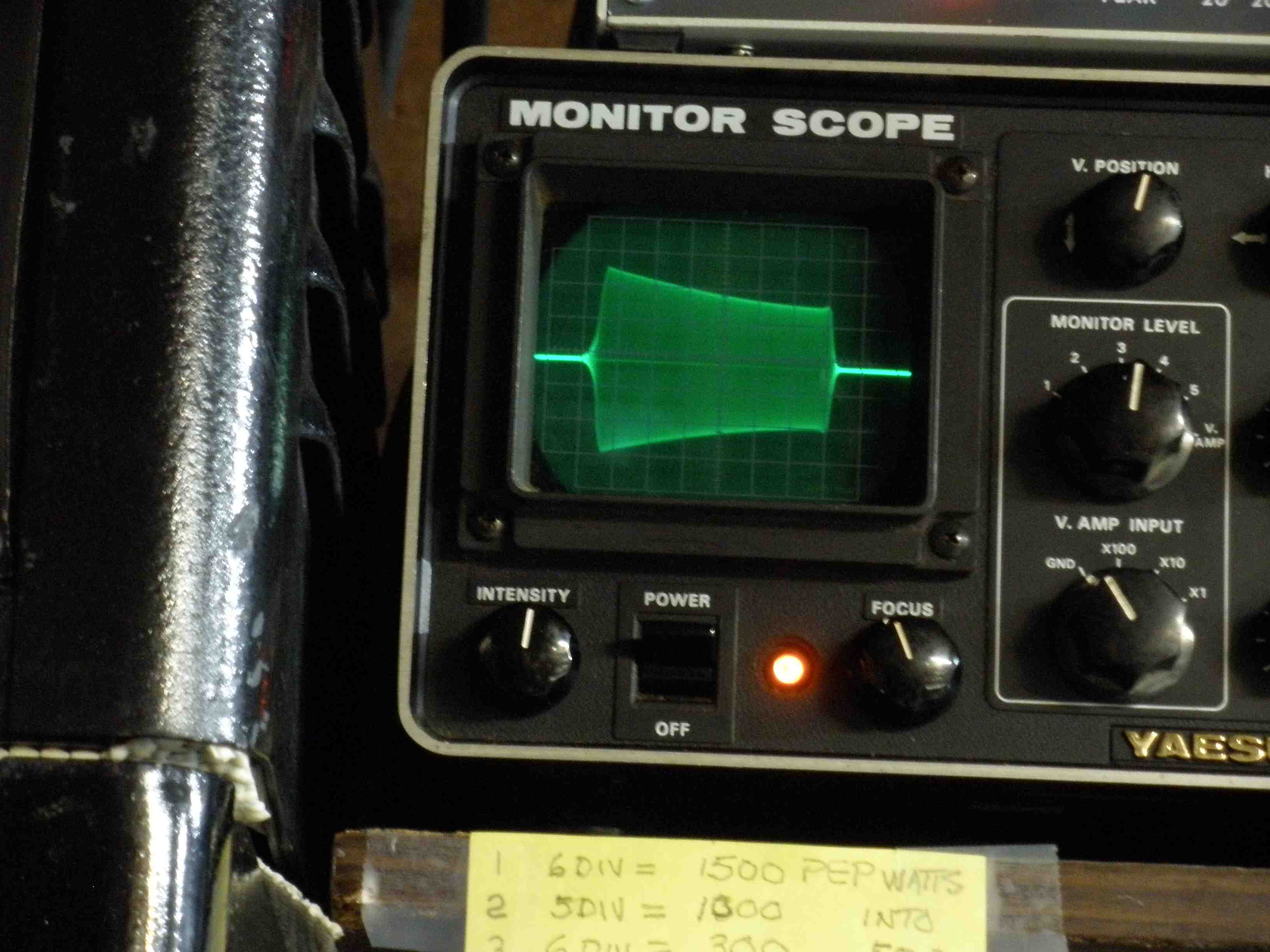
For a very complete explanation of how the grid block keying circuit works, see: Changing the VFO coax to RG-62/U allows you to make the cables 5 feet long instead of 3 feet, due to the lower capacitance per foot. This maintains the resonance of L51 to the Johnson design. If you examine the output waveform on the 1.75 - 2.0 range, you will find that L51 resonates to 80 meters. The resulting scope trace shows the 80 meter harmonic output stronger than the 160 meter fundamental. This gives more drive for 80 and 40 meters. The 40 meter VFO output is tuned to 40 meters, as expected. When the VFO is modified to cover 5 or 6 MHz, reduced output occurs, but L51 tunes very broadly and tripling works. Allow warm up time for frequencies above 40 meters. Quadrupling to 12 meters may not provide sufficient grid current and requires another padder capacitor and VFO frequency range. I did not add 12 meters to my rig, but you can use these ideas to do so. I found chirp minimal. I did not change the original VR tube or 6AU6 types, as some have recommended. The time sequence element of this modification starts the oscillator immediately (delaying the transmitter output), and holds the VFO "on" long after the key is released, giving similar stability as keeping the VFO running all the time. R202 is set to keep the VFO on the verge of oscillation in key-up. Be sure to adjust the keyer control R202 and the clamp tube R30 properly. Replace the shiny shield with a black IERC shield (as used in R390) on V5 to reduce heat. See Electric Radio # 270, p 38, by N0DMS. Keying voltage is now about 4 mA at 67 Volts Negative. Use the HamGadgets UKA-3 keyer to protect the output of your solid state keyer: KEYING WAVE FORMS WITH GRID BLOCK KEYING MODIFICATION: CLICK TO ENLARGE
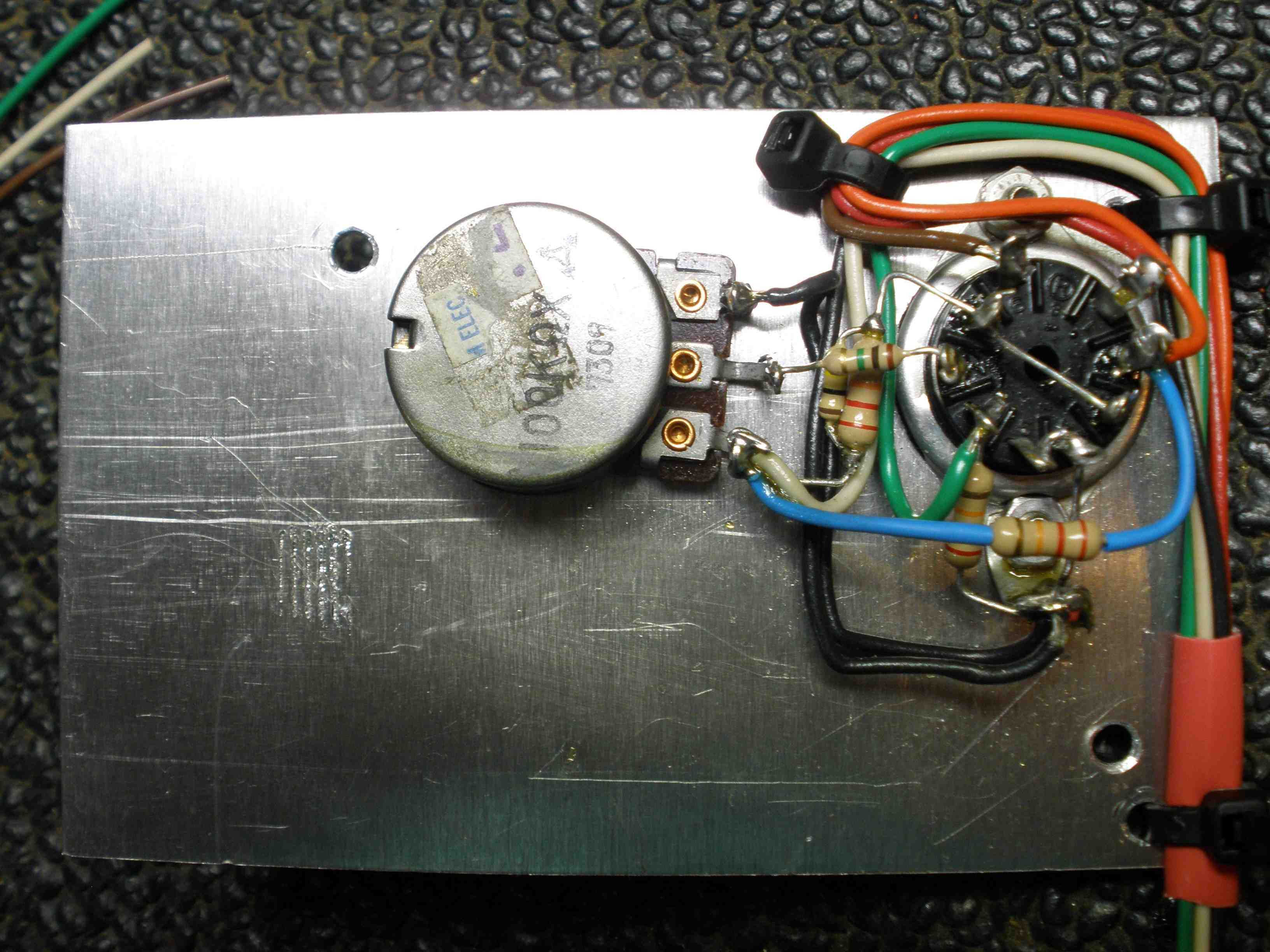
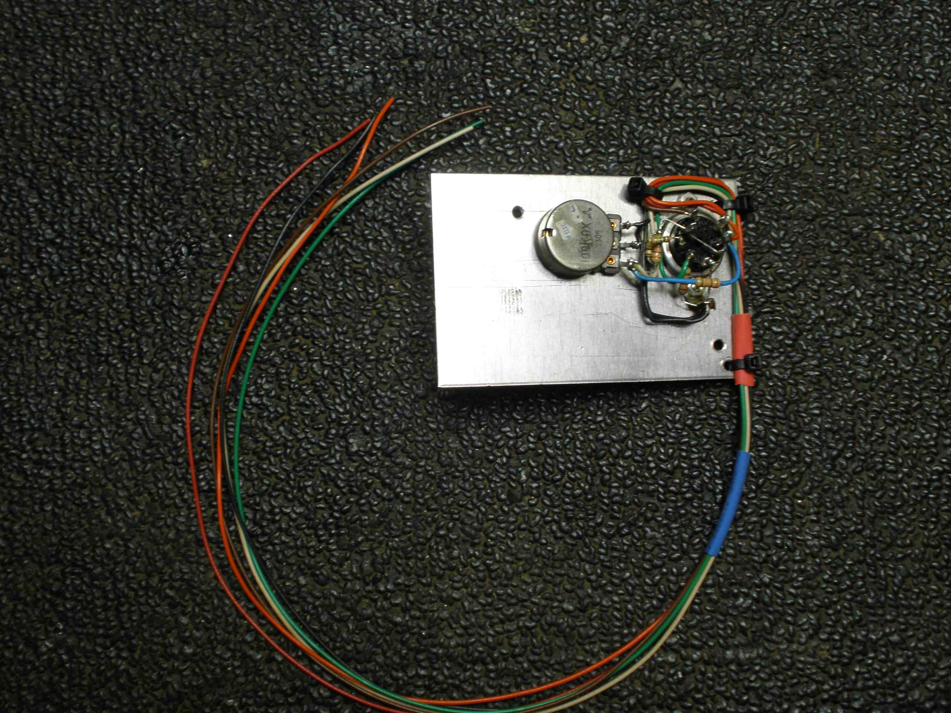
CONSTRUCTION OF KEYER CHASSIS AND INSTALLATION; CLICK TO ENLARGE
VFO MODIFICATION FOR WARC BANDSI was surprised to find the standard Viking II will cover all the WARC bands. The basic ranges of the 250-122 VFO are 1.75 - 2 MHz and 7.0 - 7.425. 11 meters can be modified to cover either 5.05 - 5.075 and/or 6.02 - 6.056 MHz with the addition of a mica padder capacitor in parallel with C56. I mounted a miniature toggle switch on the rear panel of the VFO to select 30 meters (33 pF) or 17 meters (100 pF). 60 meters (5.3 - 5.405) works using the third harmonics of the existing 1.75 - 1.8 MHz. Be sure to use a frequency counter to get exactly on "center frequency". I added a counter output BNC on the back, with a piece of RG-174/U. Strip a very short bit on the free end and place about 1/4 inch near the buffer plate tuning capacitor wire. WARNING: This circuit has +350V DC, so insulate it well and use care to avoid shock or damage to equipment. Use a frequency counter to verify you do not transmit on the shortwave broadcast bands: 49 meters, 31 meters, 25 meters, or 19 meters. Antenna tuners which are parallel tuned (EFJ matchbox), L network (Ten Tec 238), or a Pi network are also low pass filters which will reduce harmonics which fall outside the ham bands. (A "T" match of common design is a high pass filter which doesn't reduce harmonics.) A single band antenna also will help. Modern transmitters use a Pi-L design which provides 35 dB harmonic rejection. To finish my rig, I bolted the 250-20 low pass filter to the back of the Viking II with brackets made by WA2LXB, just like his CDC, to avoid TVI and FM BC interference. Many of my neighbors still receive off air programming.
The Johnson Viking I made medium power AM accessible to many in 1949, before competition from Heathkit and others. Before that, the only alternative was homebrew or surplus. The Viking II and its modifications kept this early ham gear state of the art until the 1960s, when SSB became the most popular mode. E F Johnson served its customers well by providing field updates. Using the E F Johnson factory modifications "A", "B", and grid block keying modification makes operating the Viking II a pleasure. It works far better than the DX-100s I have owned. It also puts out 130+ watts CW on the WARC bands, something that none of its contemporaries are capable of doing. The separate external VFO makes this possible, while dramatically lowering drift due to heat. The Viking II has much lower drift than my Valiants had. With the simple reliability modifications described in Electric Radio # 368 and the neutralization modification in Electric Radio # 367 and 368, it is a stable, reliable performer. A Valiant only provides 1.76 dB or about 1/3 of an S unit bigger signal. The Viking II is my favorite vintage transmitter. Use the tuning charts and information in the manual to clarify the tuning procedure. This is an "expert mode" transmitter with a lot of knobs, so set the 3 band switches correctly. For complete information integrating the Johnson Viking 122 VFO with the Johnson Viking II for WARC band operation and installation details of the Johnson Grid Block Keying Modification, go to: WARC BAND OPERATION OF VIKING II AND CDCIt is possible to use even a standard Viking II on all the currently
available WARC bands (60, 30, 17, and 12 meters). This information shows
how to use a slightly modified 122 VFO or a synthesized VFO to have fun
on the WARC bands with this vintage classic. Be sure to include the
carbon resistor on the grid of the VFO 6AU6 to prevent oscillation. This is the only correct schematic for the Johnson 250-122 VFO.
It includes R55 (22 ohms) directly at the grid of the 6AU6 oscillator
tube to stop VHF oscillation above 80 meters. I only use NONINDUCTIVE
carbon or OX or OY type 150 ohms for R55. It also includes the complete
text and schematics for the grid block keying modification. Don't forget
to replace R51 (Chernobyl resistor) with a 5 watt unit. I even replaced
the AUDIO pot with a pot including a switch to turn off the 807
filaments when on CW for extended periods. I was surprised to find the standard Viking II will cover all the WARC bands. The basic ranges of the 250-122 VFO are 1.75 – 2 MHz and 7.0 – 7.425. 11 meters can be modified to cover either 5.05 – 5.075 and/or 6.02 – 6.056 MHz with the addition of a mica padder capacitor in parallel with C56. I mounted a miniature toggle switch on the rear panel of the VFO to select 30 meters (100pF) or 17 meters (33 pF). 60 meters (5.3 – 5.405) works using the third harmonics of the existing 1.75 – 1.8 MHz. Be sure to use a frequency counter to get exactly on "center frequency". I mounted a counter output BNC on the Viking II rear, with a piece of RG-174/U. Remove the shield from a very short bit on the free end and place about 1/4" near the buffer plate tuning capacitor wire. WARNING: This circuit has +350V DC, so insulate it well and use care to avoid shock or damage to equipment. Changing the VFO coax to RG-62/U allows you to make the cables 5 feet long instead of 3 feet, due to the lower capacitance per foot. This maintains the resonance of L51 to the Johnson design. If you examine the output waveform on the 1.75 – 2.0 range, you will find that L51 resonates to 80 meters. The resulting scope trace shows the 80 meter harmonic output stronger than the 160 meter fundamental. This gives more drive for 80 and 40 meters. The 40 meter VFO output is tuned to 40 meters, as expected. When the VFO is modified to cover 5 or 6 MHz, reduced output occurs, but L51 tunes very broadly and tripling works. Allow warm up time for frequencies above 40 meters. Quadrupling to 12 meters may not provide sufficient grid current and requires more circuitry. I did not change the original VR tube or 6AU6 types, as some have
recommended, since the grid block keying mod may depend on those
components. Furthermore, I found drift acceptable with the original
parts. The time sequence element of this modification starts the
oscillator immediately (delaying the transmitter output), and holds the
VFO "on" long after the key is released, giving similar stability as
keeping the VFO running all the time. R202 is set to keep the VFO just
below the verge of oscillation in key-up. Adjust the keyer control R202
and the clamp tube R30 per the EFJ manual. Keying voltage is now about 4 mA at 67 Volts Negative. Use the HamGadgets UKA-3 keyer to protect your solid state keyer:
Here is a table comparing some of the VFOs available. All tests are performed on the 40 meter VFO range, since that is the range most prone to drift. The capacitors are smaller, and the inductor construction is more critical on that range in most designs. Also, the 80 meter range is used on fundamentals. The 40 meter range is multiplied up to 4 times; the drift is also multiplied by 4 on 10 meters. That is the most important consideration in the choice of 40 meters for my test. NOTE: The VF-1 could not be set to exactly to 7.0 MHz, due to the
tuning rate.
Due to backlash, the HG-10 could not be set to exactly to 7.0 MHz.
DRIFT is defined as the change from 20 minutes warm up to final time of 2
hours.
Raw data is provided so you can interpret it differently if you wish.
In any event, the stock Johnson 122 and HG-10 are tied as the best of
the simple VFOs.
The HA-5 heterodyne VFO is better, but is not in the same class due to
its complexity. You can also use a solid state synthesized VFO. | |||||||||||||||||||||||||||||||||||||||||||||||||||||||||||||||||||||||||||||||||||||||||||||||||||||||||||||||||||||||||||||||||||||||||||||||||||||||||||||||||||||||||||||||||||||||||||||||||||||||||||||||||||||||||||||||||||||||||||||||||||||||||
| 73, Janis AB2RA |
Text size: + – |
Back to Vintage Equipment Back to AM Transmitters Back to the Home Page |