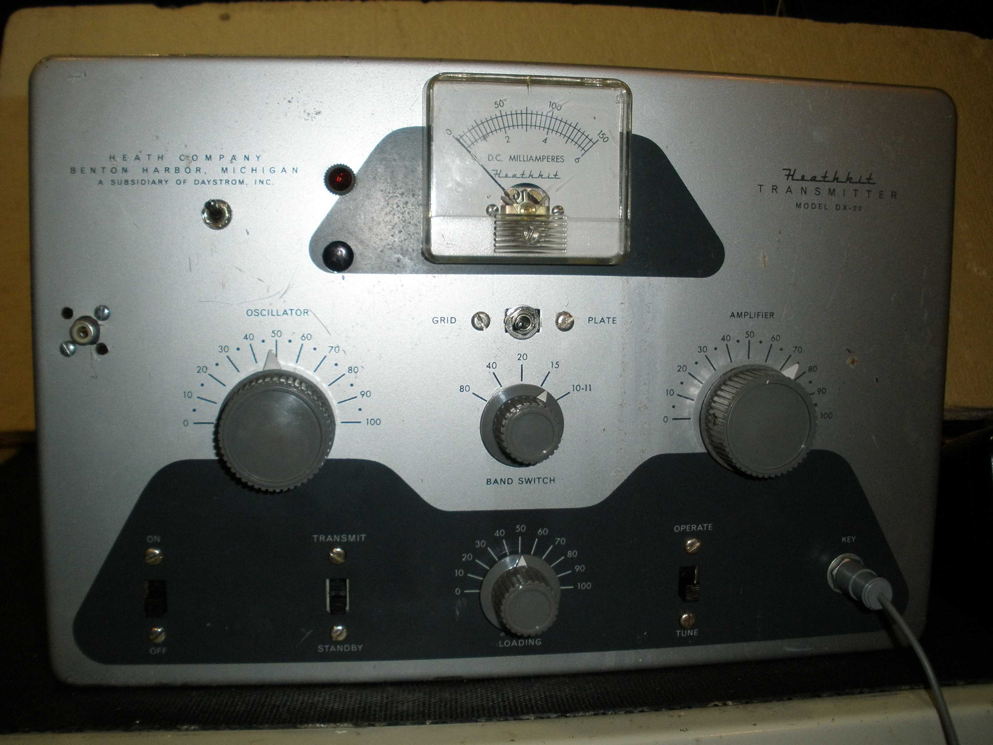
The Heathkit DX-20 (1956 - 1961) was a favorite Novice operator's first transmitter. It was the successor to the famous AT-1, the first Heathkit ham transmitter. The DX-20 is a big step up from the AT-1. It has about 35 watts output instead of struggling to make 12 watts. The DX-20 is a first transmitter kit; there are no illusions about phone or voice operation. But it can be a reliable CW rig, which can be fun even for a general operator. Its power output is about right to drive an amplifier. The next generation of this line is the short lived HX-11 (1961 - 1963). That version had provisions for controlling an antenna relay, neutralization, a better D'Arsonval meter, a built in low pass filter, and a green paint job.
The Johnson Adventurer was a competitor from 1954 through 1963. It had similar power output and tube line up. The final was an 807, not a sweep tube. Surplus 807s were cheap; 6DQ6s were relatively inexpensive at the time. Both typically are run at 45 to 50 watts input. Both are getting pricey, but you can still buy NOS or brand new production Chinese 807s. The 6AG7 operated off a lower B+. (The DX-20 ignores the maximum plate voltage spec of 300 V on the 6CL6.) The final doubled on 10 meters. There was a socket on the back of the Adventurer that could be wired for a plate or screen modulator. A screen modulator kit was available. You were on your own for the plate modulator, but WRL and Eico had them. Like the DX-60, you could get on phone at low power, but back in the late 50s and early 60s, 75 meters at night required a more powerful radio for phone. The Johnson Adventurer ($55 kit, $70 assembled) cost quite a bit more than the DX-20 ($36). The Johnson Adventurer was notorious for allowing you to tune up on 80 meters and get 40 meter output, if you did not use the dip with the most plate capacitor mesh. The later DX-20 and its descendants included a padding capacitor which was switched across the plate tuning capacitor to limit its range of tuning to prevent improper 40 meter output on 80 meters. Both the Adventurer and the DX-20 double in the final on 10 meters for reduced power output and efficiency. This is due to having only one oscillator/VFO buffer stage. It also reduces the chance of self oscillation, since neither rig has neutralization. Neutralization would be a talent above the pay grade of the Novice operator, in the opinion of the manufacturers. The main claim to fame of the DX-20 and the Adventurer was, how many components can you take out of the design and still have a working transmitter? They both proved that simplicity could be fun for a beginning ham, and were within the ability of the average Novice to build his first rig. I wish that were possible today. See my article on the Johnson Adventurer:
http://wireless-girl.com/Projects/AMTransmitters/JohnsonAdventurer/
I bought this DX-20 at a swap meet. Thankfully, I did not pay much for it, even though it was said "it works". It had seen better days. It had a lot of holes in the front panel and cabinet, and all of the tuning networks had been disconnected. The final tank coil was missing. The RF choke was damaged by rough handling. The plate padding capacitor, a fixed ceramic, was missing. This puts the tuning range of the plate capacitor to the correct range on 80 meters; it prevents accidental output on 40 meters, a common flaw in many of the rigs of this era. The plate tuning capacitor wiring had been reconfigured. The grid leak resistor was overheated and out of tolerance. The grid current measuring resistor was burned out, open. Was the meter damaged? With the obvious stress these components had been under, what kind of shape were the tubes in? The access plug to the crystal socket was missing, a minor problem compared to the rest of this basket case. Maybe the previous owner had an application that he thought justified this chop job, but it is clear from the component damage, it was ill advised. It makes me sad to see people wreck classic old gear. Is this just a parts unit now? How would I get out of this jam?
First off, I had to test the transformer and choke to see if they were good. If those were burned out, it would not be worth proceeding. The transformers in these Heathkits were known to have issues. I spent about a decade of my career in the aerospace industry, and learned the value of "failure analysis". When a component fails in that arena, questions must be answered to prevent future problems which could end future missions. An authoritative article on why the transformers are prone to failure is contained in Electric Radio #337 June 2017. Electric Radio also has information on the DX-20 in issue #55, November 1993. Dave Ishmael WA6VVL explains in detail that it is probably due to switching the center tap of the high voltage winding to ground, to control the B+ on/off function. This was a common practice in those days. It apparently causes spikes which break down the insulation on the center tap wiring, causing excessive current which burns out the transformer. With no fuse provided in this rig, it was a recipe for small fires. I had to find a fix for that. It is included in this article. As in any of these Heathkit rigs, it is advisable to operate the VF-1 VFO from a separate power supply to avoid stress on the transformer and chirp. The DX-20 does not even suggest it is possible or provide a socket on the back to attempt robbing power to run the VFO. It assumes you permanently modify the circuitry to use a VFO, and cannot go back to crystal control. I provide a switching circuit, which conveniently uses most of the holes drilled in the front panel by the previous owner. I wound up with only one goof plug, which I painted black to blend in with the panel.
Then I had to find a source for the unobtainium missing parts. W3GMS Joe bailed me out, as he has on other projects. He had a junked DX-40 and shared what I needed. Thanks, Joe.
This clearly was not a simple job of replacing bad electrolytics and touching up bad solder joints. That is the risk you run at swap meets. Kitted radios typically have a lot of bad solder joints, and possibly incorrect wiring. With the amount of modifications, this meant a long session with a copy of the schematic to mark up. The first step in this kind of repair is to get the equipment back to original. Do not attempt any modifications or upgrades until you get this part of it right, and it is tested and verified to meet original performance expectations, so you have a base line to judge any improvements.
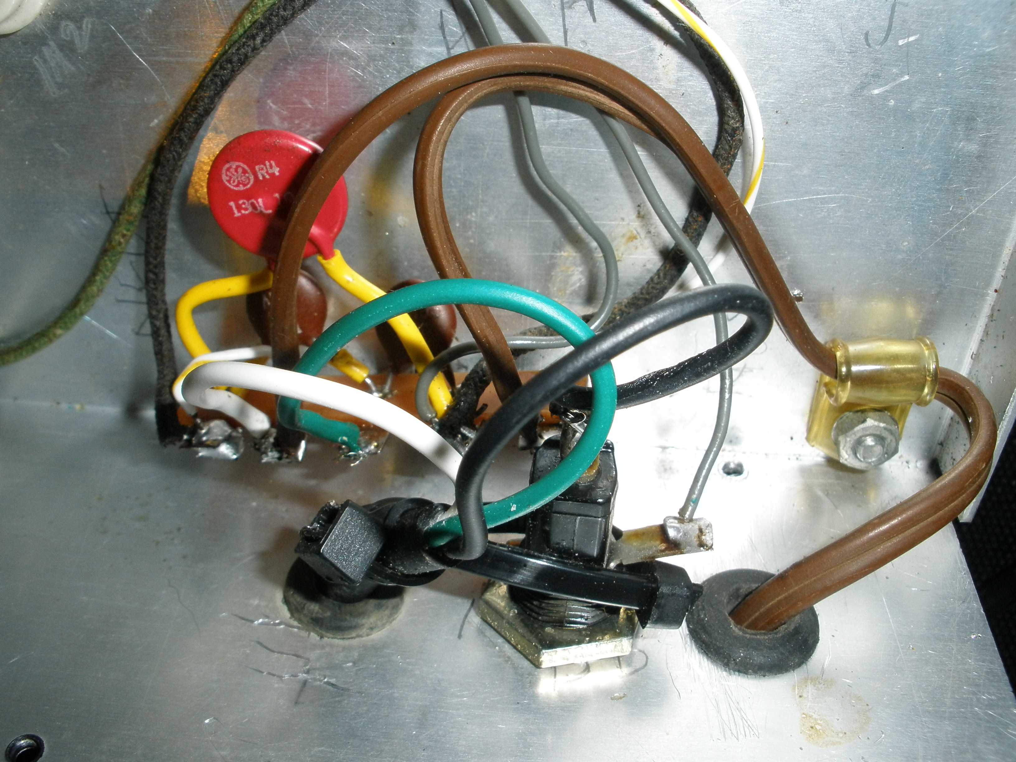
Some upgrades used in the related HX-11 will be included, along with some of my own ideas. As you can see, the meter in this one is from a DX-40. The meter shunt values from that schematic were used. I got the accuracy to 1% using some tricks I learned. They have the same ranges for grid and plate current. The DX-40 (1963), DX-35 and HX-11 used the same meter scales. The toggle switch replaces the original slide switch. These slide switches are notorious for causing intermittent meter readings. A miniature style toggle switch with a "center off" position was used to avoid drilling a hole for a full size toggle switch. The center off position is better for CW operation, and many of the rigs of the day had an "off" position to prevent wear on the meter. The Viking II and DX-100 had an off position.
If you are still using the original moving vane meter, the center off position prevents the annoying sound of the meter banging its brains out against the peg as you key the transmitter. You have to replace the switch to prevent intermittent readings anyway; consider using this idea.
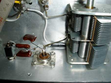
Testing the plate parasitic suppressor early in the repair process is important in any rig of this age. Cut away the wrapped wire with a very sharp wire cutter away from the resistor. Do not damage the resistor or coil. Carefully unwind the coil from one end of the carbon resistor inside. Measure the resistance; it usually goes higher with age and heat. If it reads 47 ohms +/- 10% its OK to reinstall it as is. Mine read 160 ohms, which explained the instability observed during initial tests. Replace the 47 ohm resistor with a carbon or non inductive resistor, not a standard resistor available these days. Re use the old coil. For details, read:
http://w8ji.com/vhf_stability.htm
If you have no new old stock carbon 47 ohm resistors, buy only these:
https://www.ohmite.com/ox-oy-series/
If you do not fix this problem before further testing above 40 meters, the rig will oscillate and damage may result. This is the cheapest and most effective way to fix this problem. Do not be enticed by expensive fancy parasitic suppressor kits. You can do this. The parasitic suppressor kits are a waste of money, and do not work as well as the original design. W8JI gives the full scoop on that issue.
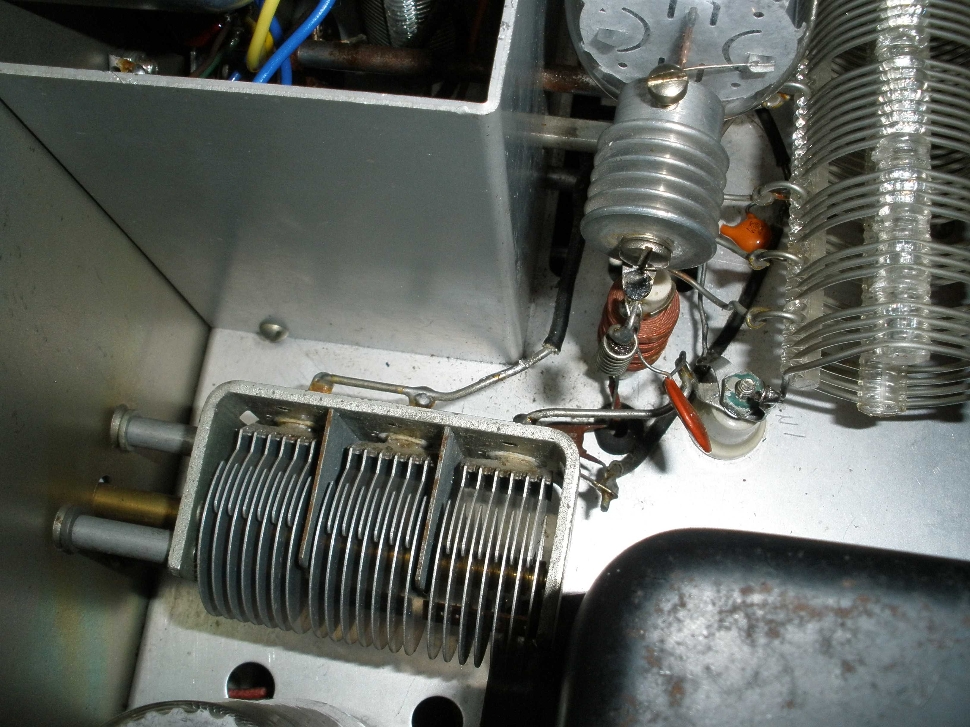
I replaced the missing output stage plate tank coil with one from a DX-40, because it was available. Are they interchangeable? Yes. The physical fit is perfect. The specified plate current is the same. The approximate plate voltage is 500 V in the DX-20 and 600 V in the DX-40. The approximate plate impedance is calculated according to Ohm's law: R= E/I. The error is about 20%, and can be compensated by the plate tuning control. More error than 20% comes from loading the rig into an SWR commonly encountered on 80 meter dipoles cut for center band. Don't overthink this; its close enough for good performance. I speculate the DX-35 plate tank coil would work just as well. The table below is the result of my tests after replacing the parasitic suppressor resistor and installing the DX-40 tank coil. A link to a general purpose Pi Network calculator for any transmitter may be provided here later.
The frequency chosen for the following table is in the CW band. On 80 meters, the plate tank circuit Q can vary significantly across the band. This should be optimized for CW for this transmitter. Line voltage was 120 VAC, which results in slightly higher plate voltage than originally designed. Optimum plate current was 115 mA (at 1% calibration) and resulted in maximum clean output in each case, except for 10 meters. I would go with the same 115 mA plate current value for all bands, since the output on 10 meters might have been unwanted harmonics due to increased grid drive. The grid drive in the table is the optimum drive for maximum clean output after plate tuning is correct. Excessive grid drive does not increase performance, except for doubling on ten meters. On ten meters, grid drive in excess of 4 mA does not deliver any more usable clean power, and may damage the tube. The same 40 meter crystal was used for all the upper bands. Output and grid drive is down on 15 meters (the third harmonic), due to having only one oscillator/driver tube. Also, lead inductance and other inefficiencies common in all rigs on the upper bands take their toll. Drive is higher on 10 meters because the driver tube output is on 20 meters, the second harmonic, and the 6DQ6 doubles to 10 meters, requiring higher drive. Power was measured with a digital watt meter into a 50 ohm dummy load. Most bands deliver about 70% efficiency, the optimum maximum value for class C operation. The 6DQ6 plate should not show any color.
| FREQ MHZ | WATTS OUT | GRID MA |
| 3.58 | 35 | 2.0 |
| 7.03 | 36 | 2.0 |
| 14.06 | 36 | 2.0 |
| 21.09 | 33 | 1.5 |
| 28.12 | 26 | 4.0 |
I recommend 2 mA grid drive on all bands except ten meters, which should be 4 mA. There is no grid drive control resistor on this rig, so you will have to tune off to one side or the other to reduce it to spec. Check your keying for chirp; you may find one side is better than the other. Some crystals may not start if keyed on the low frequency side (grid capacitor more meshed). If you can get 2 mA grid drive on 15 meters, use that. I had to settle for less.
Your restored rig should have similar performance. Low grid drive may be due to a weak 6CL6 or flaky crystal.
Low grid drive is bad for the 6DQ6, since it has only grid leak bias, no DC protective bias, and no clamp tube.
If the 6DQ6 is not operated with proper bias, it is not running class C, and can cause damage.
Low output or low off resonance plate current with normal grid drive may indicate a weak 6DQ6 or low B+ from a weak 5U4.
With normal drive, off resonance plate current pins the meter.
High plate current which cannot be dipped to normal values on 40 meters and up indicates problems in the tank circuit.
On 80 meters, the loading capacitor is not big enough, and a fixed capacitor must be switched in for that band only.
It is normal when operating into a 50 ohm load to not get a plate current dip or have higher than normal plate current values at dip,
even with the loading control set to maximum capacitance. The solution is to mount a miniature center-off toggle switch near the loading capacitor on the back of the chassis.
On one side of the switch, install a 500 V dipped mica capacitor equal in value to the loading capacitor.
On the other side of the switch, install another mica capacitor double the value of the loading capacitor.
These fixed capacitors in parallell with the variable loading capacitor will give sufficient range for operation on 80 meters.
You may find them necessary if you are using a shortened antenna (with a loading coil) on 40 meters.
You should never use them on 20 meters and up.
The HX-11 was improved by adding contacts to the TRANSMIT/STANDBY switch to send 115 VAC to an antenna relay, back in that day, a Dow Key type relay.
Of course, at these power levels, a smaller relay with a 120 VAC coil will work just fine. I strongly recommend that you use one relay for the antenna switching, and a SEPARATE relay for receiver muting.
Another approach would be to use an E.F. Johnson electronic T/R switch (discussed elsewhere on this web site). DO NOT USE A JOHNSON T/R SWITCH WITH A SOLID STATE RECEIVER! Use only with tube radios.
This will require replacing the original SPST switch with a DPDT switch.
While you are at it, this is an opportunity to address the transformer failure issue.
One author found that the center tap of the high voltage windings of the transformers in the "DX" series, the 20, 35, and 40, are prone to arcing from inductive spikes when switched.
To solve this problem, permanently ground the center tap of the high voltage transformer. This does mean the HV is ON all the time, though.
To prevent accidental keying of the transmitter, use the second set of contacts to interrupt the keying line to the front panel jack.
Inadvertently bumping the key will now no longer transmit into a "no antenna" condition caused by the antenna relay.
I did this mod to mine, and it worked ok. Don't even think of powering an external VFO from the DX-20.
Of course, adding a fuse to any of the DX series transmitters is essential for protection, especially since the HV is always ON now.
A heater to cathode short on either tube could be catastrophic. Failure of a 5U4 or the filter capacitors would also cause damage.
A fuse is just good policy, and the choice of omitting it is a false economy.
It is easy to mount a fuse holder near where the AC line cord enters the DX-20.
I also added a switch for VFO/xtal choice. In my rig, the holes were in the front panel from a previous owner.
In your case, a more original version of this can be done by fabricating a bracket to mount the switch inside the opening where the crystal plugs in.
To implement this mod, study the DX-20 manual. Heathkit did not give exact wiring for a switch, assuming you would only operate VFO if you upgraded.
Its simple to install the changes allowing you to select either your favorite frequency from a collections of "rocks" or transfer to a VFO, as needed.
Sadly, crystal control works these days only if you are calling CQ. Nobody seems to tune off frequency for an answer, as we did back in the 50s.
I salvaged a meter from a junked DX-40, along with its multiplier resistors (necessary for correct calibration).
The bouncy moving vane meter was just too irritating. I replaced the original slide switch with a miniature center off toggle switch.
I have had a lot of fun with this DX-20. I consider it superior to the DX-35 and DX-40, because it does not have series connected driver tubes and a notoriously unreliable rotary function switch.
It makes no pretense of powering an external VFO, and you should NOT attempt that. Build a separate power supply for your VFO, to eliminate chirp and transformer failure.
As a final touch, I added a large heat sink style plate cap for the final tube.
Resist the temptation to replace the 5U4 with solid state diodes. The 6CL6 is already over ratings, and this will make it worse.
In an AM only rig, this might be viable. But on CW, the current goes from zero (except for bleeder current) to maximum, and the voltage will soar key-up.
You could reduce the values of the bleeder resistors, but that would stress a transformer which was not designed for that amount of current.
You could get fancy with a series zener diode in the solid state rectifier, and would it work? Maybe, maybe not.
Just stick with the 5U4, they are still cheap and plentiful.
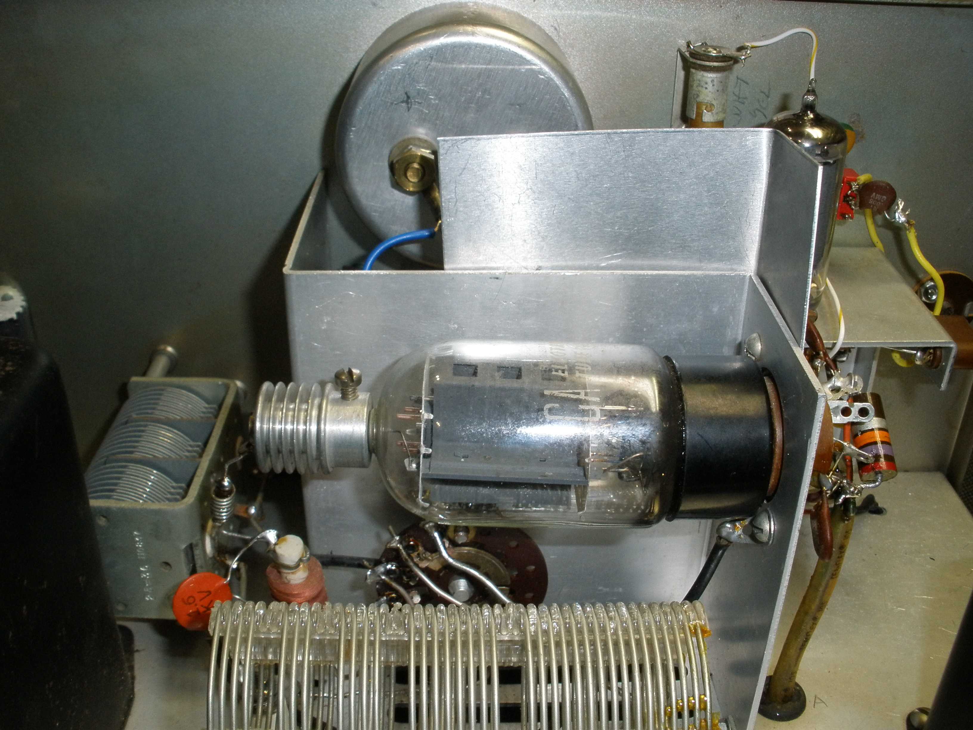
I added a piece of sheet metal to reduce coupling between the 6DQ6 and the 6CL6. This improves stability. Could I have used a tube shield on the 6CL6?
Yeah, but the metal piece was cheaper and easier. Replacing the socket to accept a shield would have been a hassle.

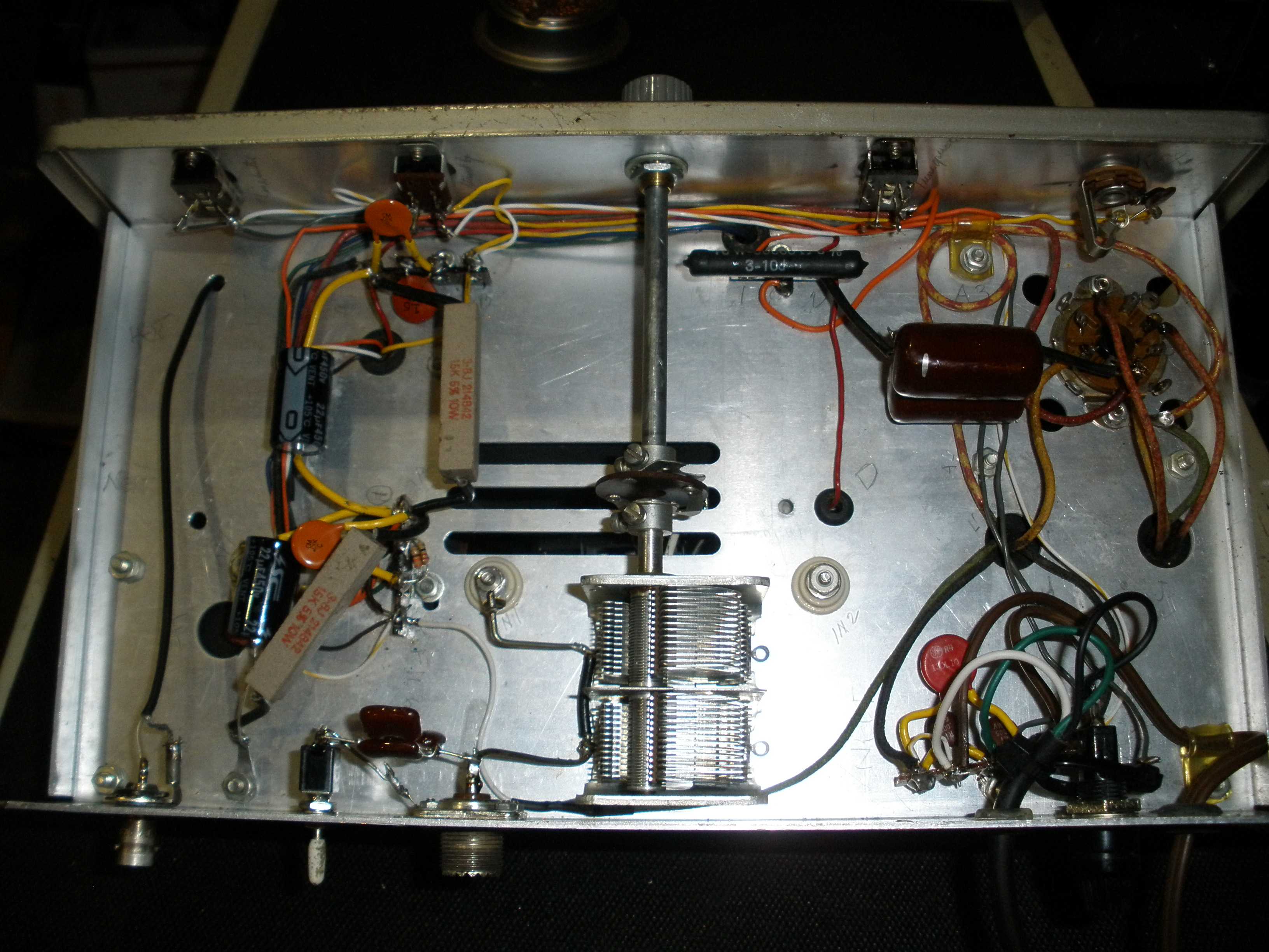
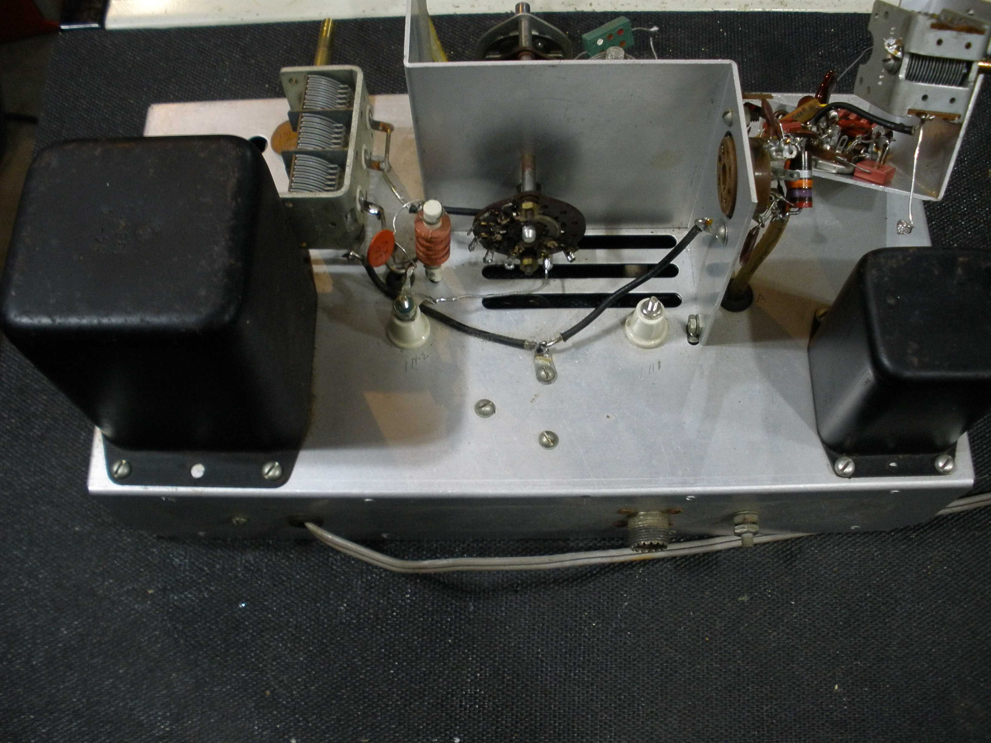
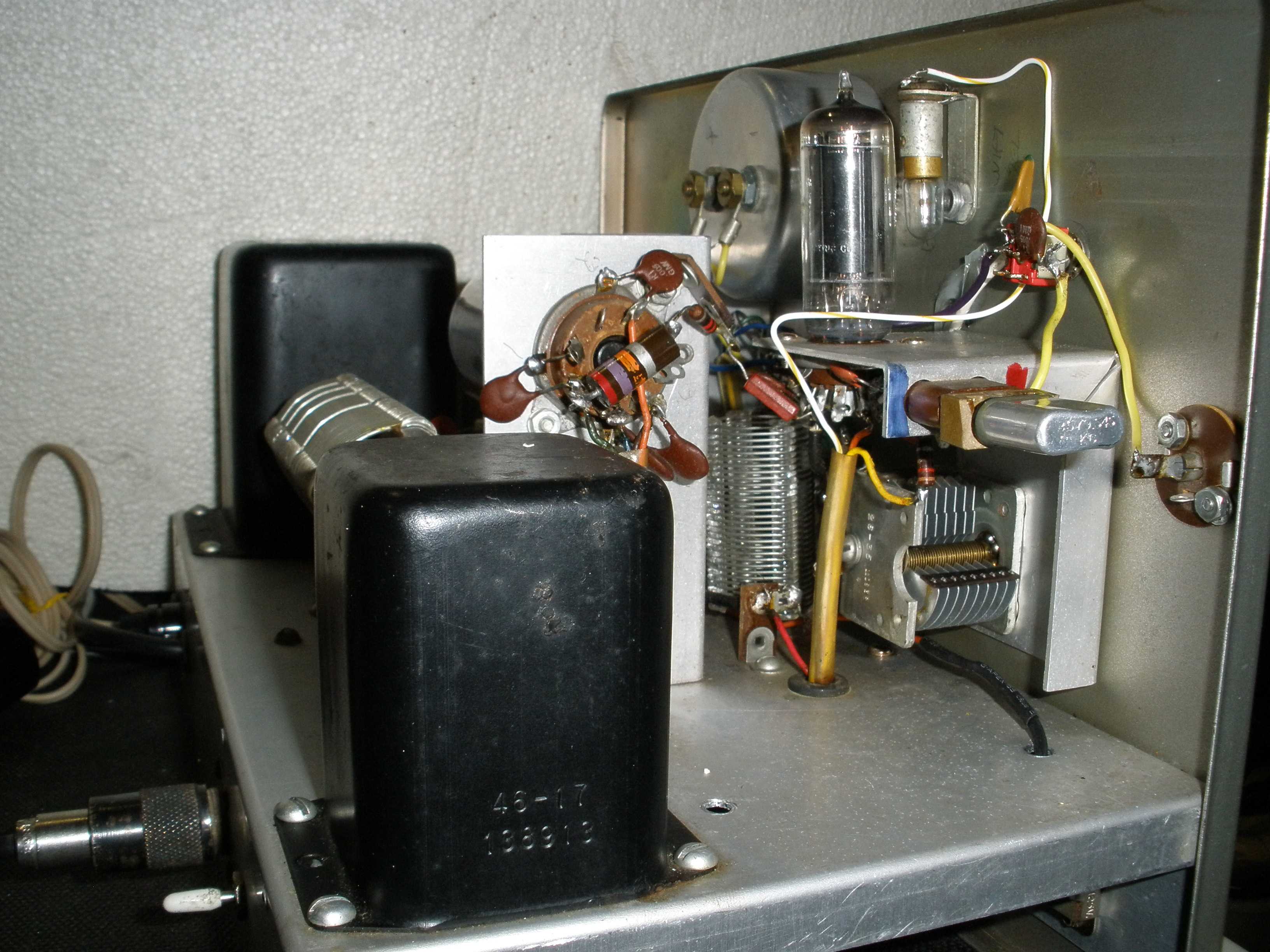
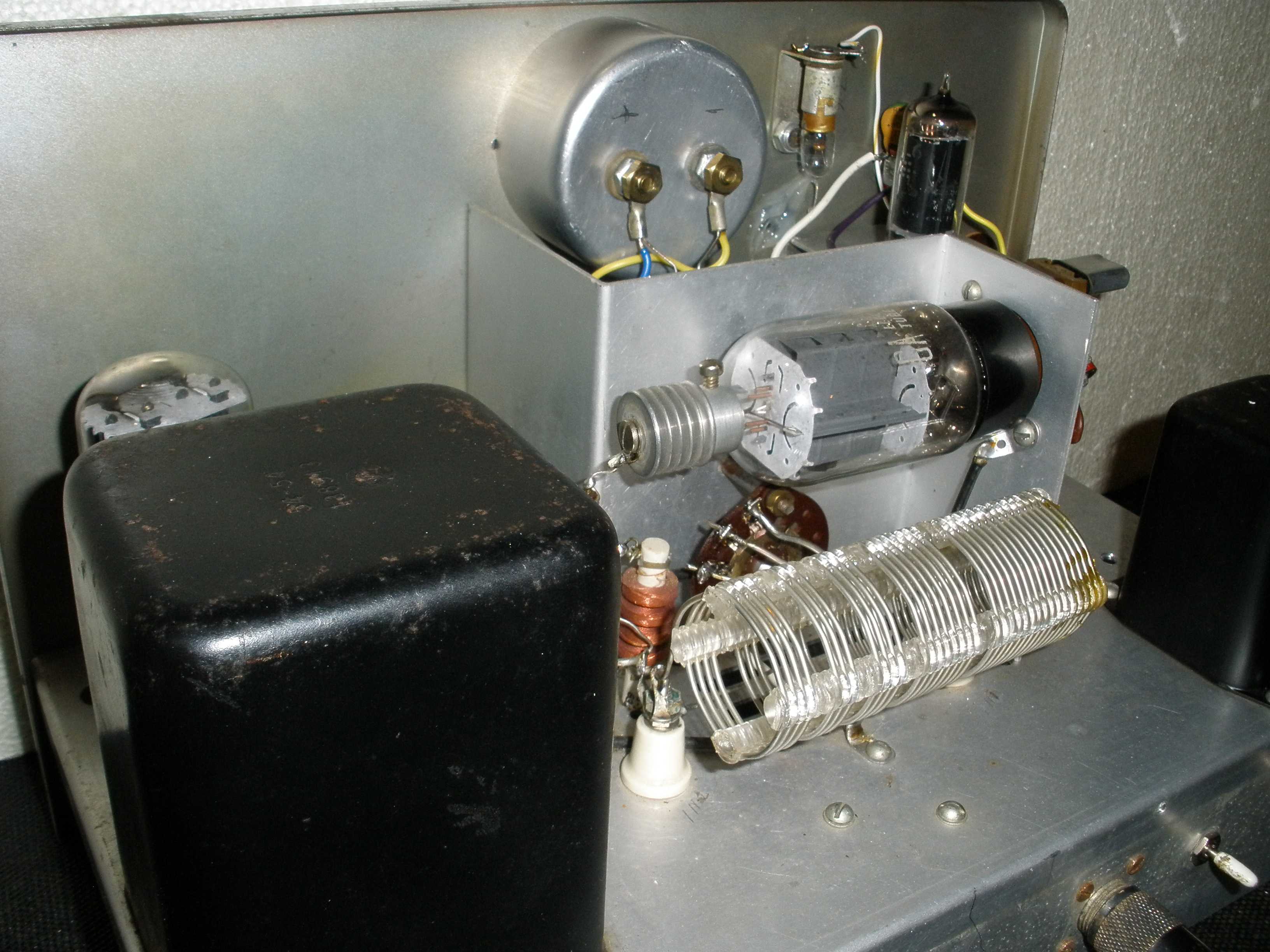
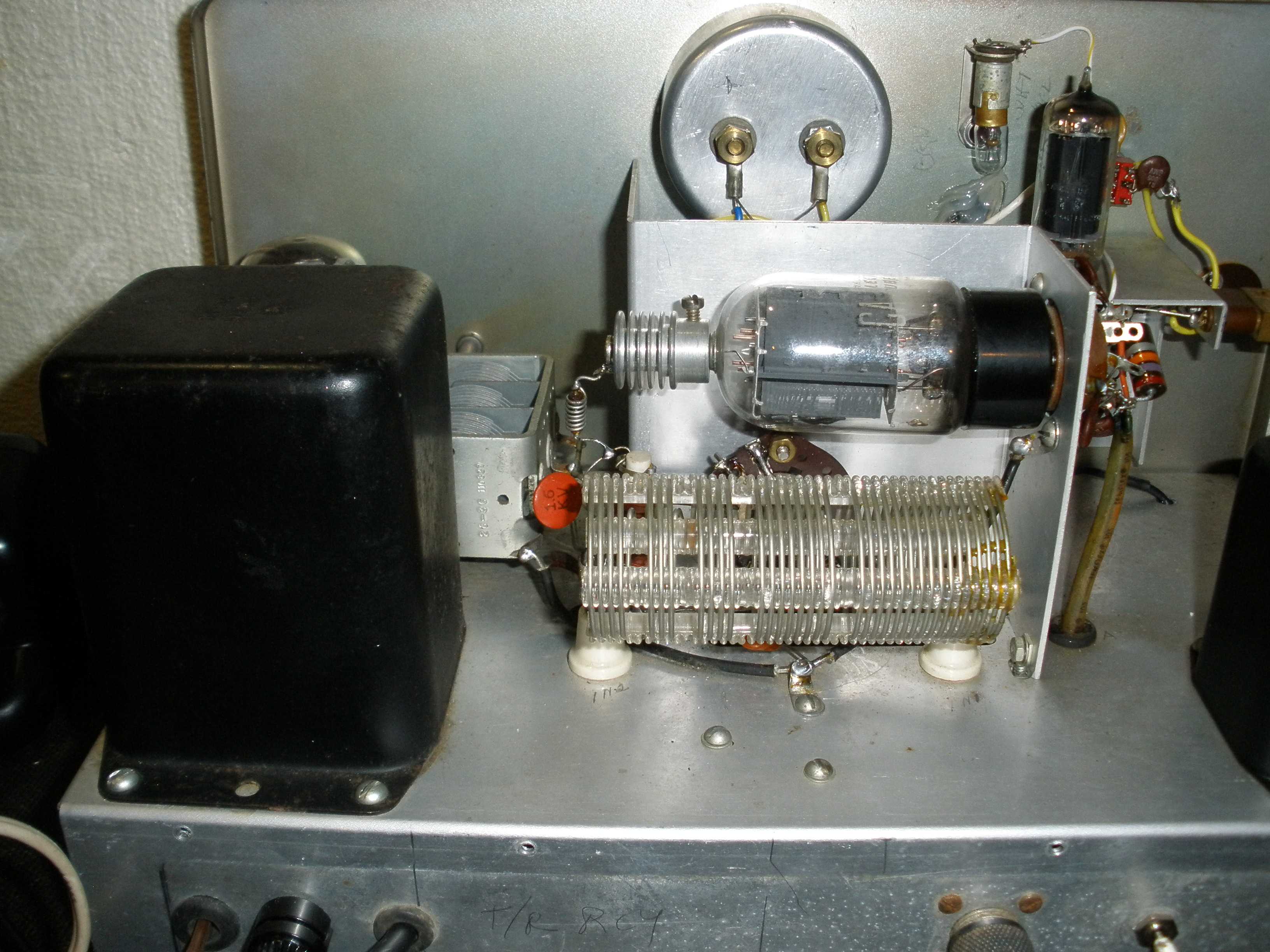
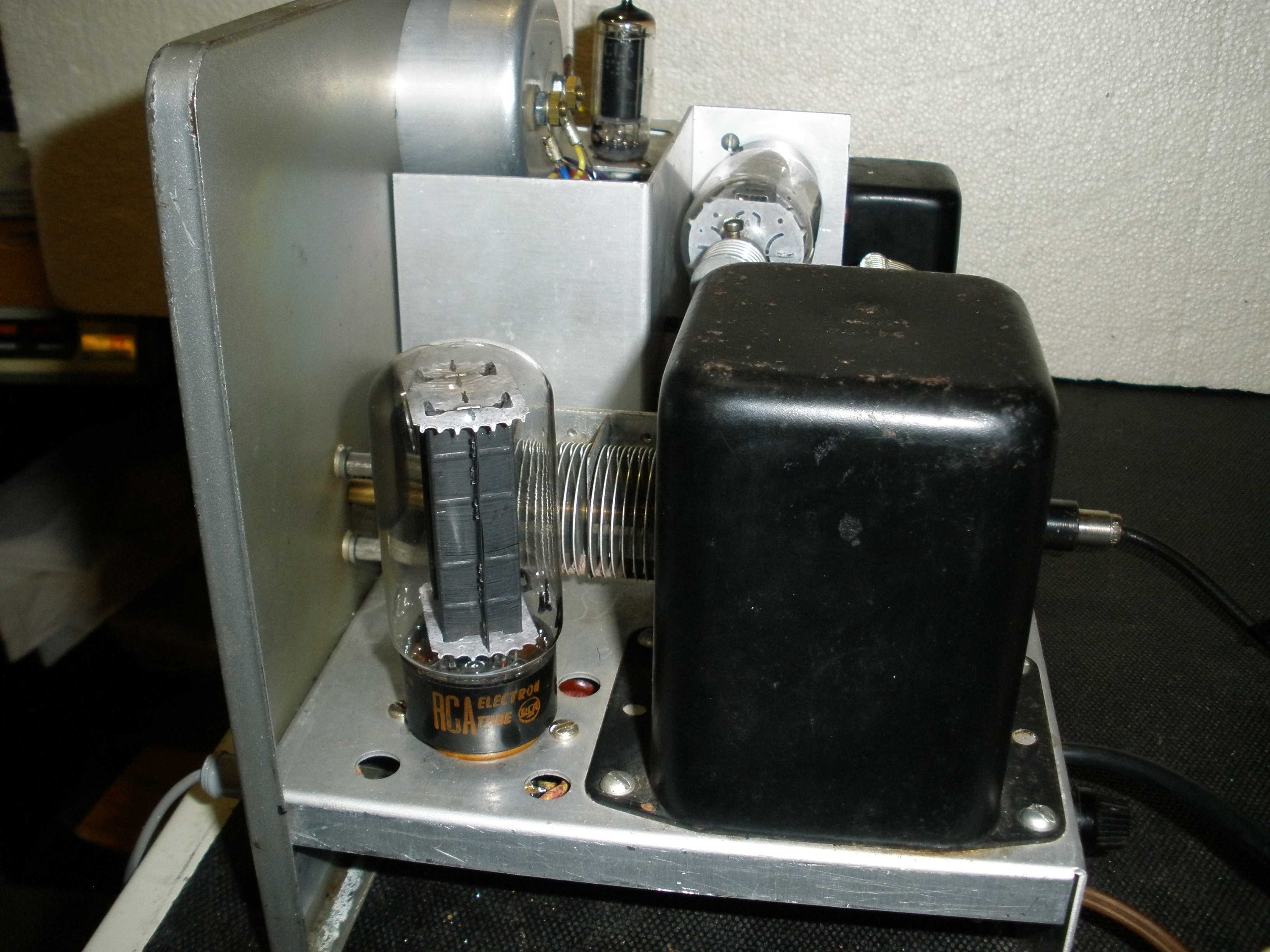
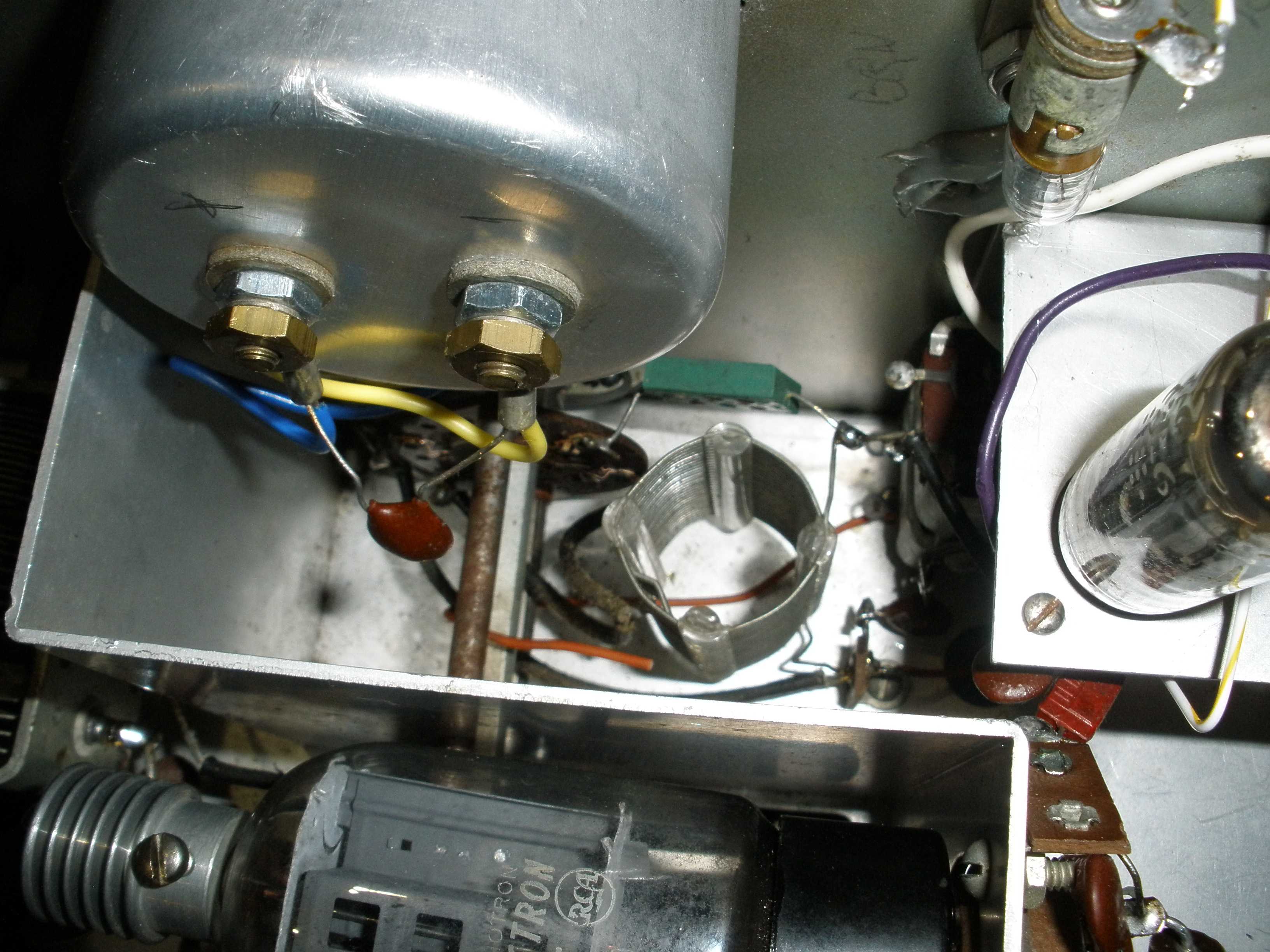
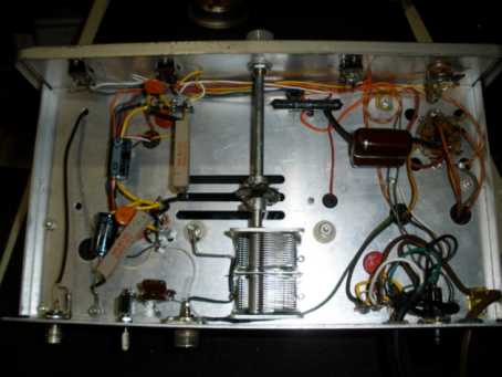
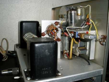
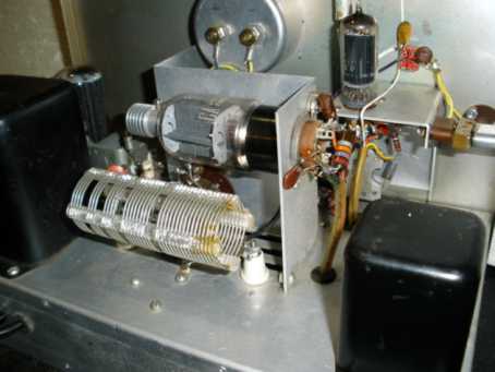
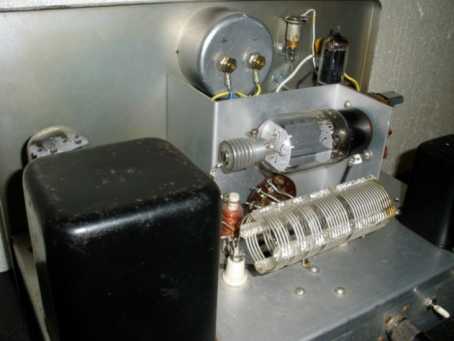
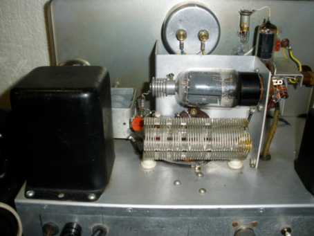
The photo gallery below is added for you to see what the work looked like when completed.
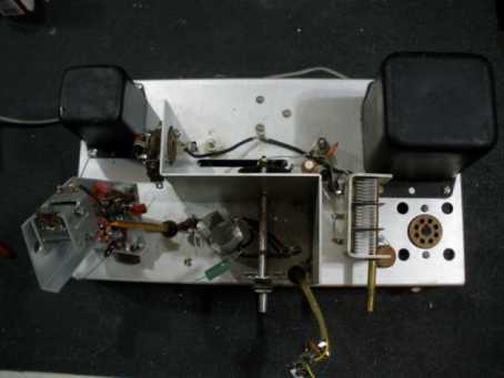
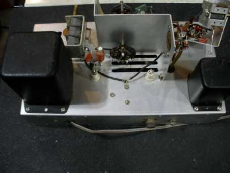


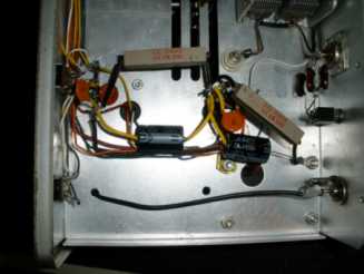
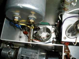
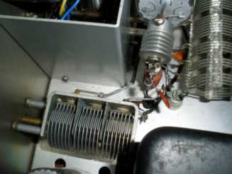 Top⇑
Top⇑HEATHKIT DX-20 TRANSMITTER WITH VF-1 VFO SPURIOUS OUTPUT DATA
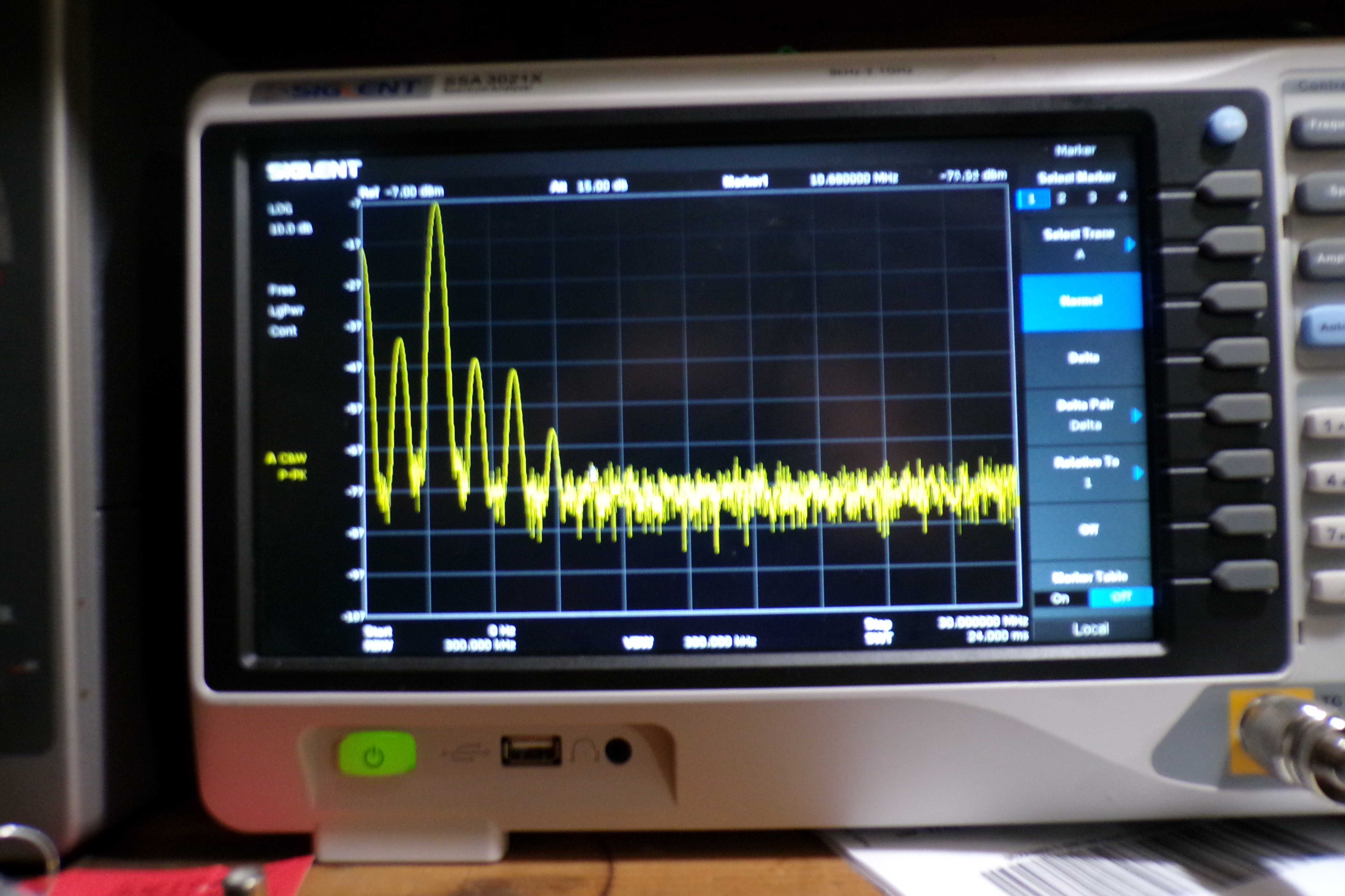
I am using a new toy, a Siglent SSA 3021X spectrum analyzer to characterize the spurious output of my projects, after I complete them.
This data should be relevant to any stock unmodified DX-20 with the matching VF-1 VFO. Keep in mind that the VF-1 has three ranges:
160-80-40 with a fundamental output of 1.750 MHz to 2 MHz, 40-20-15-10 with a fundamental output of 7 to 7.4 MHz, and an "11 Meter: range which can be modified for 5.05 - 5.075 MHz for 30 meters,
or a 6 MHz range which will allow 17 meter operation on most transmitters with 15 meter capability. It will soon become obvious that a VFO with an 80 meter or 3.5 MHz fundamental output
would produce less spurious output than a VFO with 1.75 MHz output.
The current FCC Part 97 rules state:
"97.307 Emission standards
(d) For transmitters installed after January 1, 2003, the mean power of any spurious emission from a
station transmitter or external RF power amplifier transmitting on a frequency below 30 MHz must be at
least 43 dB below the mean power of the fundamental emission. For transmitters installed on or before
January 1, 2003, the mean power of any spurious emission from a station transmitter or external RF
power amplifier transmitting on a frequency below 30 MHz must not exceed 50 mW and must be at
least 40 dB below the mean power of the fundamental emission. For a transmitter of mean power less
than 5 W installed on or before January 1, 2003, the attenuation must be at least 30 dB. A transmitter
built before April 15, 1977, or first marketed before January 1, 1978, is exempt from this requirement."
The purpose of this part of my restoration page is to alert users of this vintage equipment to the potential for interference from spurious emissions from this vintage gear. While the FCC
has "grandfathered" this old equipment, it may attract unwanted attention. One method to correct the spurious emissions would be to build a fancy band pass filter. A cheaper and simpler
solution would be to use a Johnson Matchbox to couple the DX-20 to the antenna. This would add a tuned circuit and link coupling and reduce spurious output another 10 - 15 dB or more.
Use of monoband resonant antennas might also help.
Some of the photos are a bit fuzzy, so I provide a text analysis of the screen shot shown. I need to learn more about my new toy to see if I can do screen grabs that are sharper.
In the meantime, here is the data.
All spectum photos are with a sweep from zero to 30 MHz.
For comparison to a contemporary rig with a link coupled output, see my AT-1 page, which has spectrum analyzer data also.
The DX-20 is a big step up, not just for power output and functionality, but generally much cleaner spectrum as well.
https://wireless-girl.com/Projects/AMTransmitters/Heathkit-AT1/
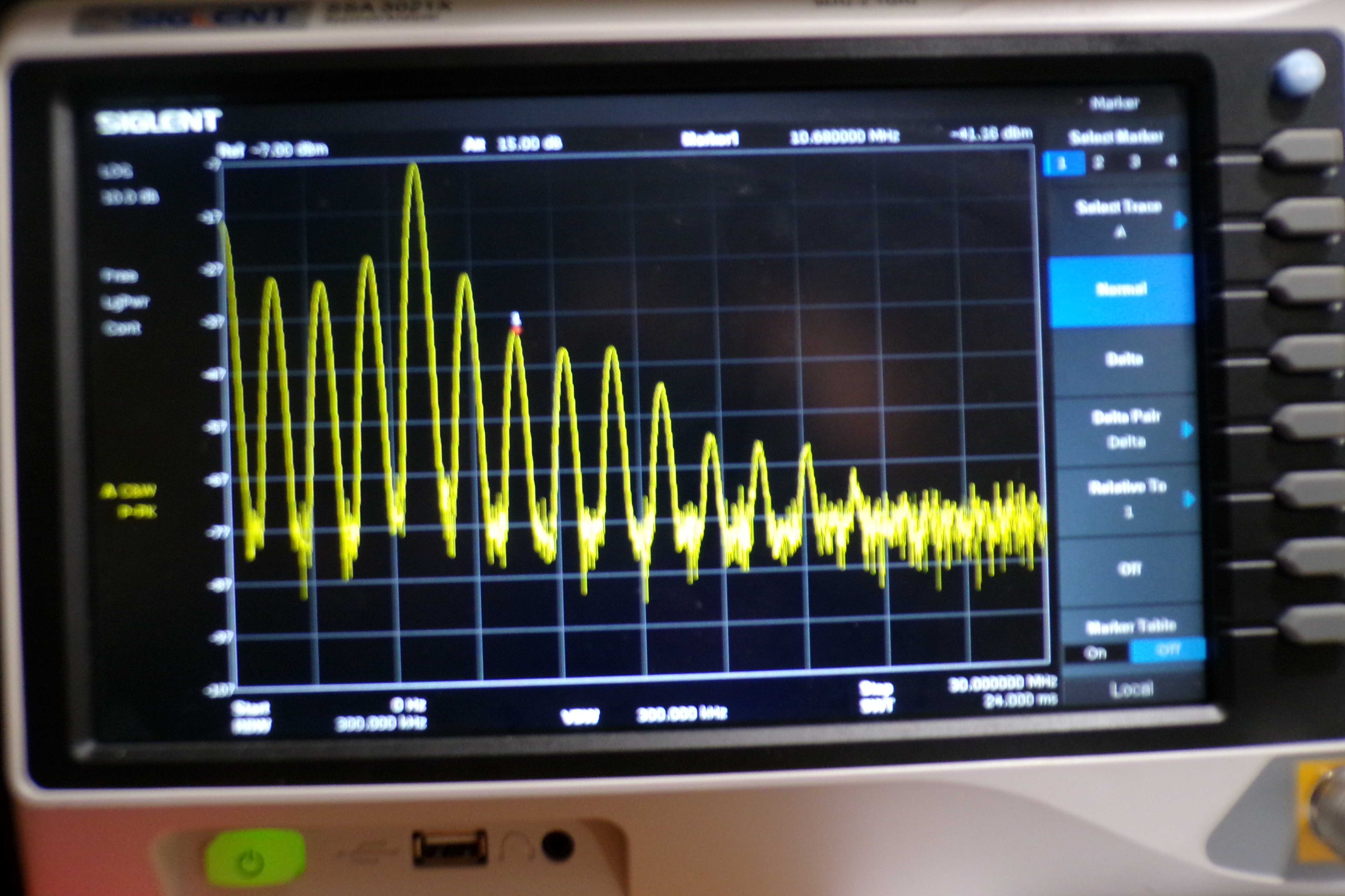
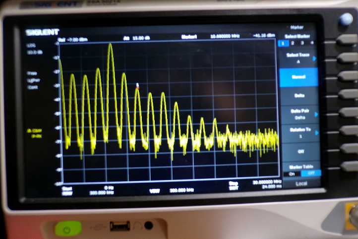
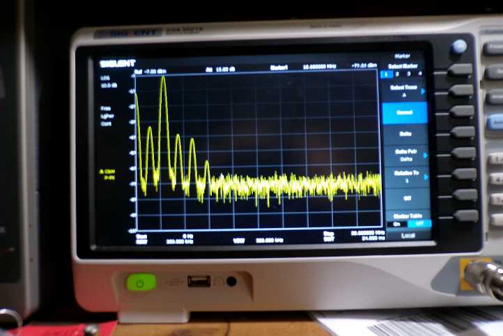 80 METERS WITH 1.75 MHZ VF-1 VFO
5.36 -40 dB
7.3 -38 dB
8.9 -58 dB
10.68 -55 dB
NOTE low pass PI network output suppresses higher harmonics pretty well.
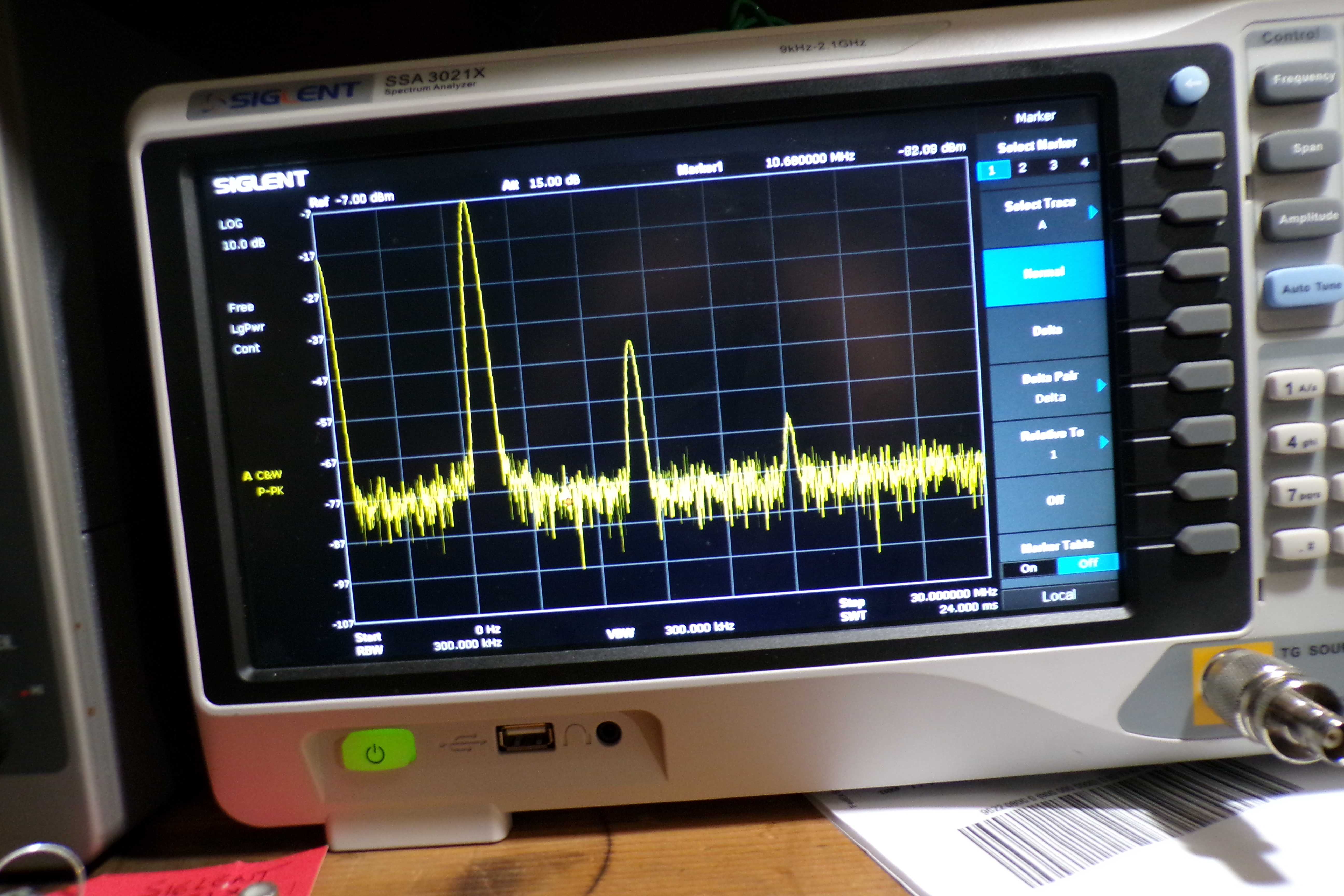
 40 METERS WITH 1.75 MHZ VF-1 VFO
Use a 7 MHz VFO setting instead of 1.75 MHz.
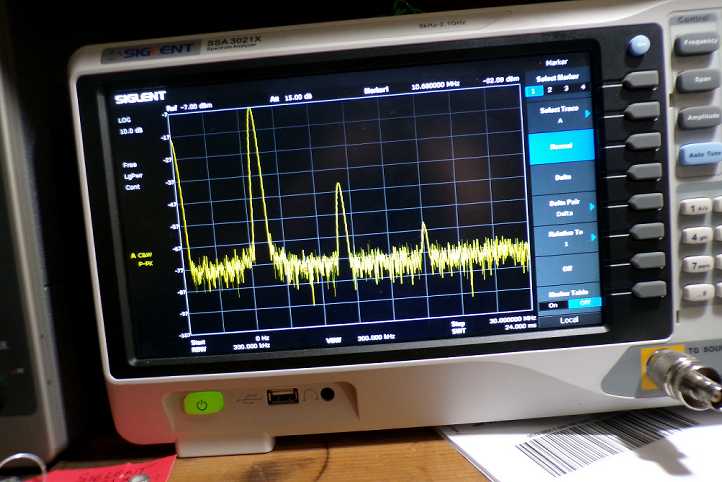 40 METERS WITH A 7 MHZ VF-1 VFO
21.16 -55 dB
PI network keeps it pretty clean above this.
Do not use the 160-80-40 VFO range to operate on 40 meters, use the 40 meter range, to avoid a messy signal.
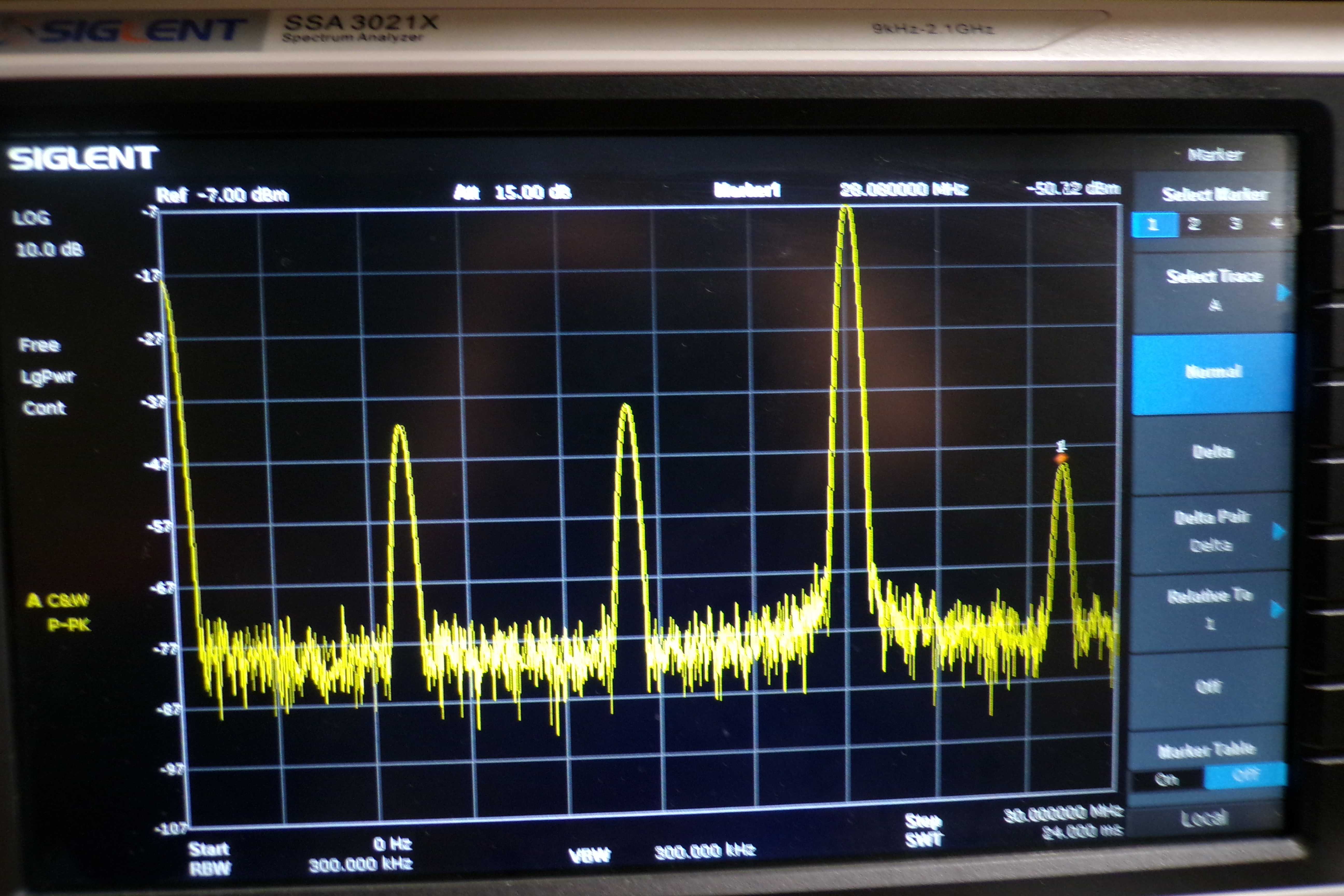
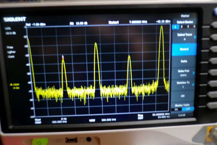
 15 METERS WITH A 7 MHZ VF-1 VFO
14.1 -31 dB
28.1 -43 dB
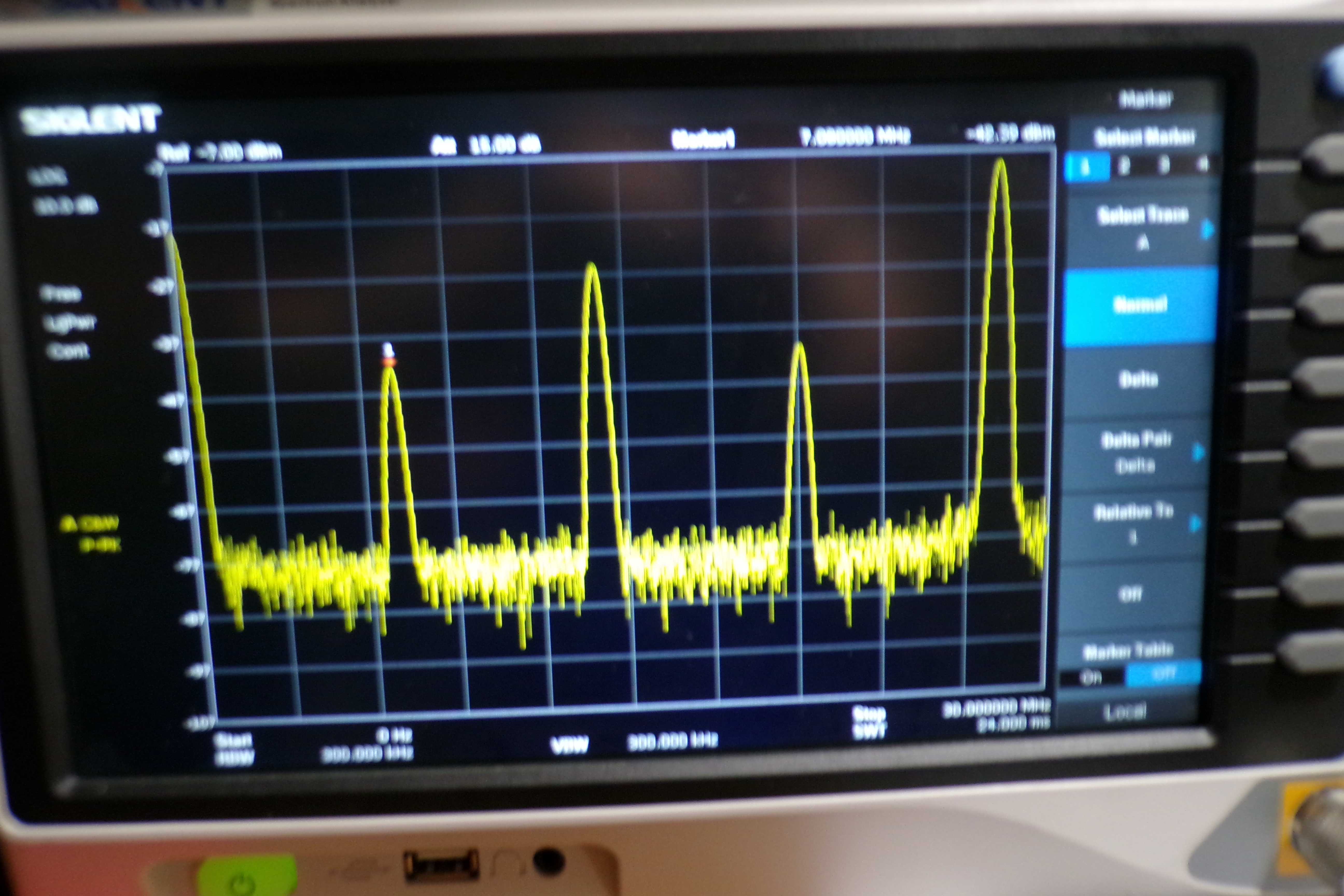
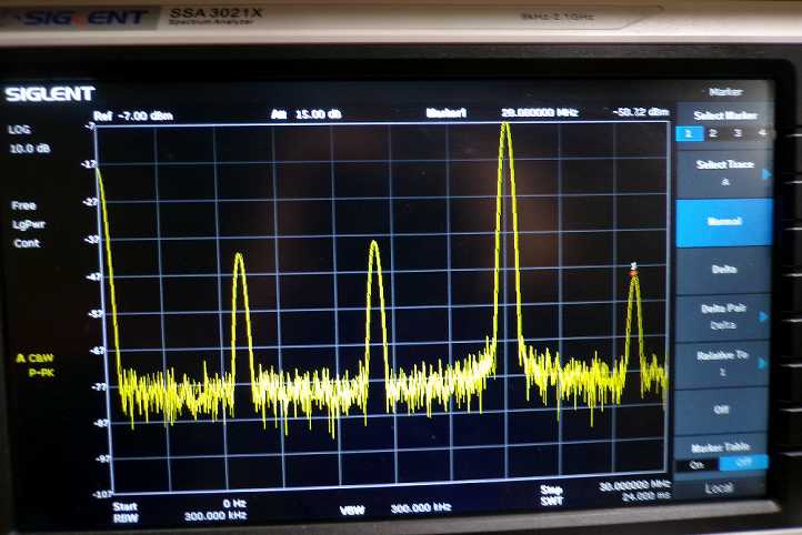
 10 METERS WITH A 7 MHZ VF-1 VFO
Note the prominent spur on 20 meters when operating on 10 meters.
7 - 33 dB
14 only -18 dB ! At least this spur is within a ham band.
21 - 31 dB
Not shown:
35.5 -42 dB
42 -42 dB
HEATHKIT DX-20 TRANSMITTER HA-5 VFO SPURIOUS OUTPUT DATA
I repeated the measurements with a Hallicrafters HA-5 VFO. I did not have a Heathkit HG-10, but it would probably be even cleaner, since it does not have crystal heterodyne frequencies.
The HA-5 is a heterodyne VFO with a 5 - 5.5 MHz variable oscillator and a crystal controlled mixer. In most cases, a dramatic improvement is shown. Similar results would have been seen
using 80 meter crystals for 80 meters and 40 meter crystals for 40 meters and up. NOTE: Items with asterisk * are probably
by products of the crystal oscillator or mixing scheme which would not be present with the Heathkit HG-10 or crystals.
80 meters with 80 meter VFO HA-5
7 -37 dB
10.6 -55 dB
40 meters with 40 meter VFO HA-5
1.56* -36 dB (This is 5 - 3.5 MHz mixing product)
5.52* -43 dB
8.64* -53 dB
12.56* -62 dB
21.12 -50 dB
20 meters with 40 meter VFO HA-5
1.6* -55 dB
5.48* -63 dB
7.08 -33 dB
8.6* -43 dB
12.56* -43 dB
15.64* -48 dB
21.12 -40 dB
28.12 -38 dB
15 meters with 40 meter VFO HA-5
7.04 -36 dB
12.52* -63 dB
14.08 -32 dB
19.56* -43 dB
22.68* -50 dB
28.12 -50 dB
10 meters with 40 meter VFO HA-5
1.64* -55 dB
5.48* -63 dB
7.04 -35 dB
8.56* -62 dB
12.52* 57 dB
14.08 -18 ! DX-20 doubles in final on 10 meters.
15.6* -58 dB
19.52* 60 dB
21.12 -32 dB
26.48* -42 dB
29.68* -44 dB
34.93* -45 dB
42.26* -48 dB
BOTTOM LINE: Using a 3.5 MHz VFO or crystal for 80 meters, and a 7 MHz VFO for 40 and up produces a remarkable improvement in spurious outputs.
Also, all products worse than -35 dB fall within an amateur band with the system configured as shown.
For 80, 40, 20, and maybe even 15 meters, the DX-20 is fairly safe to operate with crystals or a proper VFO as noted. For especially 10 meters, probably not.
I hope this information has been helpful guidance in how to operate your vintage equipment, to minimize spurious output.
|